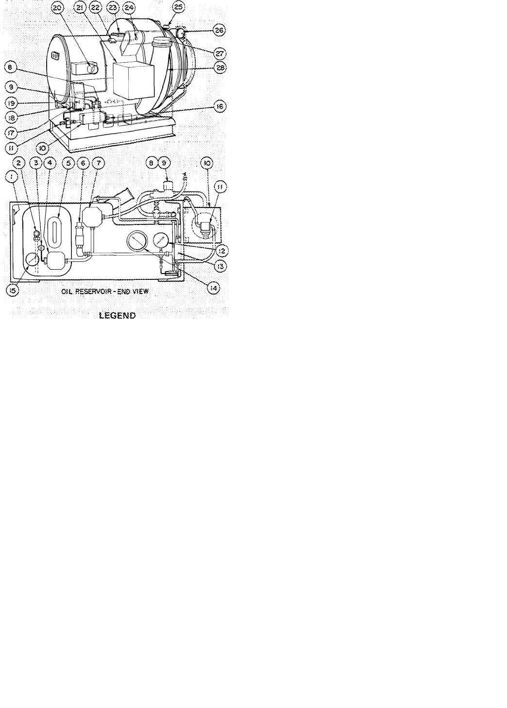
1 Serial Numlser idenritica-
Tior> Piste
2 Oil C^iarairvg Valve
3 Gii Heater Tl>erfr;ost3t
4 Oil Heater ; ern-.inal Sox
5 Oil Reservoir Siijf.t Glass
6 Oil-Pressare Regtila-rioó
Valve. : :
7 Oil Purtiii Temrinal Sox
8 •'!=•■ Solenoid Valve
9 "G" Soteooici Vaive
tO Gii Cooler
Water-Ir, Conr>..Solenoid
Valve and Plue Cook
12 Oli-Pressore Gage
13 OiPPrsssure Oiilerenrial
Switoli
14 Bearing Temperature Gage
15 Oli XemperaTure Gage
16 Oit Cooler Wa‘-:-r-Oor
Gconeotion
17 Oil Pornp Nciirrepiate
18 Gornoressor Nameplate
19 edmpt esser Joriction Sox
20 Economlter inlet
21 Compressor Morof Terminai
Sox (Par side on most ■ :
rncdetsl: r:'.
22 Motor and Stg H i-Temp-
C'-itout iluncticrn Sox ;
23Main Searing inspection Cove'
24 EeonomiKer Darooer Ccn-
r.ection .CR 014 dniy}■ T
25 Guide yiane indicator
{gleotronte ConTrot) : :
26 Hydrau lic V-ane Motcir
27 Oispharoe StuOouT- :
28 DiscP-aige Pipe
Fig. 2 — Compressor (Electronic Capacity Control)
Machine Tightness — If machine leak testing and
dehydration was not completed at installation,
check machine tightness (including pumpout sys
tem) as described below. Dehydration must be
repeated if machine has been idle for several weeks
after initial dehydration.
Check for Large Leaks — Using one of the methods
described below, pressurize the machine to the
level listed in Table 1. Do not exceed test pressure
Listen for large leaks as the pressure builds up. If
test pressure holds for one hour, proceed with
Check for Small Leaks.
All 19CB machines may be pressurized with
cylinders of dry air or nitrogen thni the cooler
charging valve. Dry air or nitrogen charging is
preferable to purge or pumpout charging as it
ensures that moisture will not be introduced into the
machine. To pressurize with nitrogen (or dry air):
1. Connect a copper tube from charging valve to
pressure cylinder. Never apply full cylinder
pressure to the pressurizing line. Follow steps 2
thru 5 in proper sequence.
2. Open cooler charging valve fully.
3. Open cylinder regulating valve slowly.
4 Observe cooler or condenser pressure gage and
close cylinder regulating valve when pressure
reaches test pressure listed in Table 1.
Do not exceed test pressure!
5. Close cooler charging valve. Remove copper
tube.
R-11 machines may be pressurized with the
purge pump. Ensure that electrical supply to purge
pump is 120 volts. Then follow Operation 3 on the
purge valve chart.
R-1 14 machines may be pressurized with the
pumpout unit This method is detailed in the
section entitled Pumpout Procedures.
Table 1 — Test Pressures
REFRIGERANT
R-11
R-114
TEST
PRESSURE
8-10 psig
30 - 35 psig
3
4.
Check for Small Leaks
1. Pull a vacuum equal to 5 in. Hg (12 5 psia) by
using purge pump Operation 2 (R-11
machines), pumpout unit (R-114 machines) or
by applying a vacuum pump at the cooler
charging valve.
2. Charge approximately 25 pounds of the proper
refrigerant thru the cooler cliarging valve.
Pressurize machine to test pressure (Table 1)
using purge pump, pumpout unit, dry air or
nitrogen. Do not exceed test pressure
Test all joints, valves, fittings etc. with a halide
or electronic leak detector.
Check Leakage Rate
1 Install a mercury manometer (absolute pressure
type) on a tee at the cooler charging valve.
Pull 25 in. of vacuum on the machine.
Let machine stand with this vacuum for at least
8 hours
If leakage rate is less than 0.1 in. Hg in 24 hours
(0.033 in. Hg in 8 hrs), machine is sufficiently
tight. Perform Machine Dehydration.
If leakage rate exceeds 0.1 in. Hg per 24 hours,
repeat Check for Small Leaks, repair leaks and
repeat this Leakage Rate check.
Remove or valve off manometer before re
peating any pressure test.
Machine Dehydration
W.^iRNlNG: Do not attempt to start compres
sor, oil pump or purge motor even fox a
rotation check, nor app.ly test voltage of any
kind while machine is under dehydration
vacuum- Motor insuiation breakdown and
serious damage tnav result.
2.
3
4.
5.
6.


