Start-Up Demand — Steam demand by the absorp
tion machine is greatest at start-up (see Table 1 for
values).
Table 1 — Maximum Condensate Flow (Ib/hr)
VALVE VALVE INLET STEAM PRESSURE
SIZE (in.)
20 psig
14 psig
12 psig 10 psig
2
2450 2025
1880 1750
2Y2
4825 4000
3710 3430
3
8175 6760
6285 5810
4
14540 12025
11190 10350
5
21650
17900
16655 15400
When boiler capacity is unable to keep up with
start-up demand, the steam pressure will fall off.
On boilers serving only the absorption machine,
this reduction in steam pressure will have no
adverse effect on the absorption machine other
than to lengthen start-up time. However, the
increased steam demand may have an adverse
effect on the boiler, causing it to run dry and fail.
As steam pressure is reduced, the steam control
valve pressure drop will eventually limit the de
mand on the boiler provided the steam control
valve is properly sized.
On boilers serving other loads simultaneously,
the start-up demand can reduce boiler pressure
sufficiently to cause adverse effects on other
steam-driven equipment. When a reduction in
boiler pressure cannot be tolerated without up
setting other equipment, the boiler capacity avail
able for absorption machine operation (with other
loads deducted) must equal or exceed the start-up
demands. If it does not, the start-up demand can
be reduced by using demand Hmit controls, or
installing a back-pressure regulator in the steam
line(s) between the boiler and the control valve(s).
VALVE LOCATION AND PIPING - The steam
control valve should be located a minimum of 3 ft
away from the generator inlet. This is dictated by
good piping practice, to allow equal distribution of
steam in the generator tube bundle. Unequal
distribution of steam in the tube bundle may cause
a loss of capacity. Recommended steam supply
piping for low-pressure steam applications is
illustrated in Fig. 1.
STEAM CONTROt
NOTE; Separate supoiy piping "for each end of machine sizes
16JB077 thro '24,
Fig. 1 — Low-Pressure Steam (2 to 15 psig)
Supply Piping
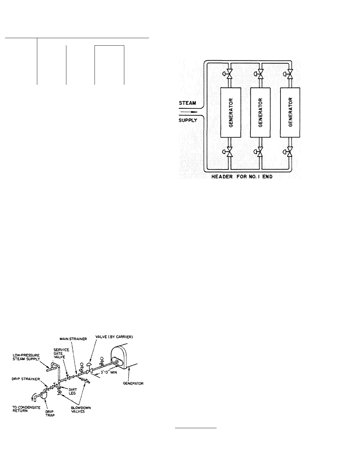
Machine sizes 16JB077 thru 16JB124 have
steam supply inlets on each end. These are to be
considered as two generators and should be piped
from a common steam header as in multiple
machine installations (see Fig. 2). Each inlet should
then be piped in accordance with Fig. 1.
HEADER FOR N0.2 END
NOTES:
1. Piping appiies to moitipie macbiries connected in paraiief
(3 shown).
2. Each end most be consdered as a separate generator.
3. The feed to each end of each generator should be piped as
shown in rig. 1.
Fig. 2 — Steam Piping For 16JB077 thru 124
Steam piping to the absorption machine should
be designed and supported to allow for thermal
expansion without imposing undue stresses on the
generator inlet. The machine is not designed for,
nor expected to act as, a piping support or anchor
for withstanding thermal stresses.
Condensate Systems — Satisfactory operation of
the absorption machine requires a condensate
handling system designed with the specific char-
acteristics of the absorption machine in mind. The
following is intended to supplement available
reference data on condensate systems such as
Carrier System Design Manual, ASHRAE Guide
and individual manufacturer’s recommendations.
ATMOSPHERIC CONDENSATE RETURN
SYSTEMS (VENTED) - These systems usually
consist of steam traps, vented receiver, condensate
pump, and condensate cooler. Fig. 3 illustrates
typical atmospheric condensate return systems. On
larger machines, with dual steam generators, the
condensate outlet from each generator must be
piped thru separate steam traps.
Trap Selection — Steam traps should be located as
far below the generator outlet as possible. Actual
pressure drop available for trap selection will
depend on exact trap location below the generator


