SVS; Reviewed:
WCH/MI 6/20/02
Solution & Interoperability Test Lab Application Notes
© 2002 Avaya Inc. All Rights Reserved.
14 of 20
Gatekeeper-ext.doc
Avaya
IP600
Avaya IP Phone
X 7702
Avaya IP Phone
X 7712
CLAN
Prowler
Avaya IP SoftPhone
X 7716
To
DHCP Server
TFTP Server
DCP
X 7704
DCP
X 7705
10.9.1.4
10.9.1.3
COL-
ACT-
STA -
123456789101112
HS1HS2 OK1OK2 PS
CONSO LE
Cajun P333T
10.9.1.5
10.50.1.0
.1
.1
. 2
FXS
X 6600
Catalyst 4000 - 4604-GWY
Cisco 4224
Cisco 3660
GateKeeper 1
10.30.1.0
.1
. 2
10.20.1.0
. 2
Cisco 1751
Gateway A
Gateway B
FXS
X 6200
Cisco 3660
Gatekeeper 2
FXS
X 6900
Cisco 1751
Gateway C
10.70.1.0
.1. 2
10.60.1.0
. 2
.1
Gatekeeper 1
Zone 1
Zone 2
Zone 3
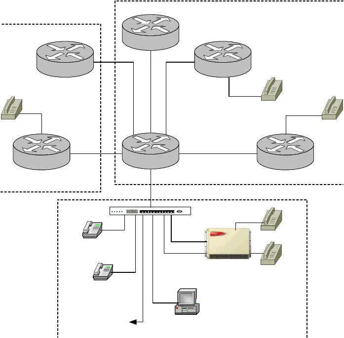
Figure 4: Multiple Gatekeeper Configuration
Figure 4 shows an additional Cisco Gatekeeper (Gatekeeper 2) as well as an additional Cisco
Gateway (Gateway C). Cisco’s Zone 2 and Zone 3 communicate directly to Avaya Zone 1,
where routing between Zones is determined. In other words, Zone 2 and Zone 3 communicate
with each other only through the role of the Zone 1 Gatekeeper .
Again, emphasis is placed on the unspecified Far-end Signaling Group created earlier (Signaling
Group 10 / Trunk Group 10). Its role has increased since it now must dedicate IP ports for
inbound traffic for both Zone 2 and Zone 3. In other words, there are now two Outbound
trunks (Trunk 6 and 12) with only one Inbound trunk (Trunk 10), therefore the Inbound trunk
port capacity should be increased to suit the network needs.


