REMOVING
THE
WATER
INLET/
DfSPENSER
VALVE
ASSEMBLY,
POWER
SUPPLY
CORD,
&
MACHINEfMOTOR
CONTROLLER
1
t
i
Efectrical
Shock
Hazard
I
i
!
Disconnect power
before
sewieing.
I
I
Replace
all
parts
and
paneis
before
operating.
i
I
?
Failure
to
do
so
can
result
in
death
or
i
1
electrical shock.
j
.
Unplug washer
or
disconnect power.
2.
Remove the console from the top
of
the
washer
(see
step
2
on page
4-2
for
the
procedure).
Power Supply
Cord
MachinefMotor
Controller
1
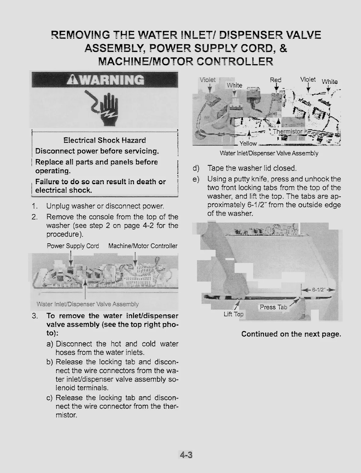
3.
To
remove the water inlet/dispenser
valve
assernbfy
(see the
top
right
pho-
to):
a)
Disconnect the hot and
cold
water
hoses from the water inlets.
b)
Release the locking tab and
discon-
nect the wire connectors from the
wa-
ter inletfdispenser valve assembly
so-
lenoid terminals.
c)
Release the
locking
tab
and discon-
nect the wire connector from the ther-
mistor.
Red
Violet
white
1ite
:--
$*s
4
-
r
;"4
L
+
.-
*--;4
)
f.#d==
+'
d'*%
%
4
C
?!%&
-
rqS&
.2
.
.
&
t
6QT*
*.-*
*
-
$>-*
'
I
Yhr:
ir
S
=+-+:--
?---&.
e
r*x-.i$Y-ip
?
-
a
-
Yellow
*
?--*2:
Water
InletiDispenser
Valve
Assembly
d)
Tape
the washer lid
ctosed.
el
Using
a
putty knife, press
and
unhook the
two front locking tabs from the
top
af
the
washer,
and
lift
the to?. The
tabs
are ap-
proximately
6-112"
from
the outside edge
of the washer.
/"
Lift
Tc
Press
Ti
Continued
on
the
next page.


