The following pages contained dimensioned drawings to be used as references when installing your machine. The drawings also have
several key points indicated , which can be referenced using the table below:
LETTER DESCRIPTION
A Electrical Connection - See Data Plate for Amperage Requirements
B Water Inlet - 3/4” I.P.S. 180
°F
Water Required
C Drain Connection - 1-1/2” I.P.S.
D Vent Collar/Splash Shield
E Vent Collar with Damper (4” W x 16” Lg x 7” High) Optional
F Steam Connection 1” I.P.S.
G Condensate Return 1” I.P.S.
All dimensions from a finished floor ar +/- 1/2” with the adjustable feet.
Utility connections, unless specifically noted, are identical regardless of direction of operation.
The material provided on this page is for reference only and may be subject to change without notice.
DIMENSION PAGES LEGENDS/TABLE DIMENSIONS
6
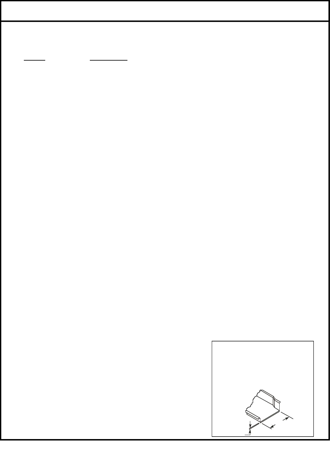
TABLE DIMENSIONS
21”
3/4”


