AP6503A
Document number: DS36000 Rev. 2 - 2
1 of 15
www.diodes.com
December 2012
© Diodes Incorporated
NEW PRODUCT
P6503A
240kHz 23V 2A SYNCHRONOUS DC/DC BUCK CONVERTER
Description
The AP6503A is a 240kHz switching frequency external compensated
synchronous DC/DC buck converter. It has integrated low R
DSON
high
and low side MOSFETs.
The AP6503A enables continues load current of up to 3A with efficiency
as high as 95%.
The AP6503A features current mode control operation, which enables
fast transient response times and easy loop stabilization.
The AP6503A simplifies board layout and reduces space requirements
with its high level of integration and minimal need for external
components, making it ideal for distributed power architectures.
The AP6503A is available in a standard Green SO-8EP package with
exposed PAD for improved thermal performance and is RoHS
compliant.
Features
• V
IN
4.75V to 23V
• 3A continuous Output Current, 4A Peak
• V
OUT
adjustable to 0.925 to 20V
• 240kHz switching frequency
• Programmable Soft-Start
• Enable pin
• Protection
OCP
Thermal Shutdown
• Totally Lead-Free & Fully RoHS Compliant (Notes 1 & 2)
• Halogen and Antimony Free. “Green” Device (Note 3)
Pin Assignments
COMP
SW
GND
BS
EN
FB
SS
( Top View )
1
2
3
4
8
7
6
5
IN
SO-8EP
Figure 1. Package Pin Out
Applications
• Gaming Consoles
• Flat Screen TV Sets and Monitors
• Set Top Boxes
• Distributed Power Systems
• Home Audio
• Consumer Electronics
• Network Systems
• FPGA, DSP and ASIC Supplies
• Green Electronics
Notes: 1. No purposely added lead. Fully EU Directive 2002/95/EC (RoHS) & 2011/65/EU (RoHS 2) compliant.
2. See http://www.diodes.com for more information about Diodes Incorporated’s definitions of Halogen- and Antimony-free, "Green" and Lead-free.
3. Halogen- and Antimony-free "Green” products are defined as those which contain <900ppm bromine, <900ppm chlorine (<1500ppm total Br + Cl)
and <1000ppm antimony compounds
.
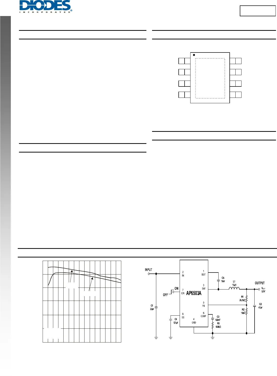
Typical Applications Circuit
Figure 2. Typical Application Circuit
LOAD CURRENT (A)
Efficiency vs. Load Current
EFFI
IEN
Y (%)
0123
V = 12V
IN
V = 5V
IN
V = 3.3V
L = 10µH
OUT
40
50
60
70
80
90
10


