Informationen zur Systemplatine 357
Systemplatine beim PowerEdge M910
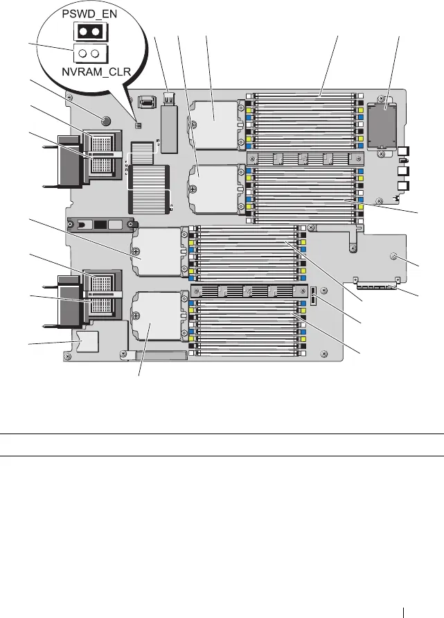
Abbildung 7-2. Systemplatinenanschlüsse beim PowerEdge M910
Tabelle 7-10. Systemplatinenanschlüsse beim PowerEdge M910
Anschluss Beschreibung
1 J_INT_USB USB-Anschluss
2 CPU2 Sockel für Prozessor 2
3 CPU4 Sockel für Prozessor 4
4 B1 – B8 Speichermodule B1 – B8
5 - Optionaler RAID-Akku
17
18
3
4
7
10
14
15
16
9
12
11
6
2
20
8
19
13
1
5


