Connection & Installation
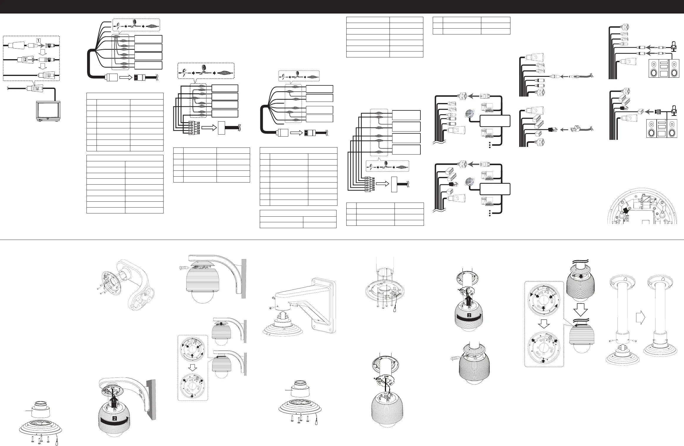
Connecting Display device
The video signal connection between the
camera and the monitor.
ALARM input connection
You can connect up to 4 alarm sensors to
the camera. Each alarm sensor should be
connected with Alarm IN COM. You can adjust
the signal state to NO (normally open) or NC
(normally closed) through the setup menu.
CAUTION:
Do not connect one alarm sensor to the
several camera’s alarm input connector.
For LNP2800I
1. Connect the RJ-45 Adapter cable to the
PORT A (RJ-45) cable of the camera.
2. Connect the alarm device to the RJ-45
Adapter cable. When connecting lines,
check and connect the color lines of the
each device correctly. Refer to the below
tables for color line information.
E
D
C
B
A
G
F
H
Alarm device
Alarm device
Alarm device
Alarm device
RJ-45 Adapter cable
Port A
RJ-45 Adapter cable
No Description Color
A RS-485 + White
B RS-485 - Orange
C NC Black
D ALARM IN COM Red
E ALARM IN 1 Green
F ALARM IN 2 Yellow
G ALARM IN 3 Blue
H ALARM IN 4 Brown
PORT A
Description Color
RS-485 + Red/White
RS-485 - Black/White
NC
ALARM IN COM Red
ALARM IN 1 White
ALARM IN 2 Light Green
ALARM IN 3 Yellow
ALARM IN 4 Pink
NOTE:
RS-485 data communication is not available.
For LNP3700T/LNP2800
1. Connect the terminal plug to the terminal
block of the camera.
2. Connect the alarm device to the terminal
plug. When connecting lines, check and
connect the color lines of the each device
correctly. Refer to the below tables for
color line information.
E
D
C
B
A
Alarm device
Alarm device
Alarm device
Alarm device
Terminal Plug
Terminal Block
No Description Color
A ALARM IN 1 Brown
B ALARM IN 2 Red
C ALARM IN COM Black
D ALARM IN 3 Orange
E ALARM IN 4 Green
ALARM output connections
Connect the alarm device to the alarm output
data port. Alarm signal output at an event
occurrence. You can set the Alarm Output to the
normal open or normal close mode.
CAUTION:
Output specifications are lowactive, open-
collector and a drive capacity of 30 V DC
0.5 A maximum. Connecting the alarm out
incorrectly may cause damaging the camera.
For LNP2800I
1. Connect the RJ-45 Adapter cable to the
PORT B (RJ-45) cable of the camera.
2. Connect the alarm device to the RJ-45
Adapter cable. When connecting lines,
check and connect the color lines of the
each device correctly. Refer to the below
tables for color line information.
E
D
C
B
A
G
F
H
Alarm device
Alarm device
Alarm device
Alarm device
RJ-45 Adapter cable
Port B
RJ-45 Adapter cable
No Description Color
A ALARM OUT [NO1] White
B ALARM OUT [COM1] Orange
C ALARM OUT [NC1] Black
D NC Red
E ALARM OUT [NO2] Green
F ALARM OUT [COM2] Yellow
G ALARM OUT [NC2] Blue
H NC Brown
PORT B
Description Color
ALARM OUT [NC1] Blue
ALARM OUT [COM1] Violet
ALARM OUT [NO1] Brown
NC
ALARM OUT [NC2] Gray
ALARM OUT [COM2] Orange
ALARM OUT [NO2] Black
NC
For LNP3700T/LNP2800
1. Connect the terminal plug to the terminal
block of the camera.
2. Connect the alarm device to the terminal
plug. When connecting lines, check and
connect the color lines of the each device
correctly. Refer to the below tables for
color line information.
D
E
F
C
B
A
Alarm device
Alarm device
Alarm device
Alarm device
Terminal Plug Terminal Block
No Description Color
A ALARM OUT [NO1] White
B ALARM OUT [COM1] Orange
C ALARM OUT [NC1] Black
D ALARM OUT [NO2] Green
E ALARM OUT [COM2] Yellow
F ALARM OUT [NC2] Blue
Connecting Network
You can control and monitor the system via
network. With the remote control (monitoring),
you can change the system configuration
or monitor the image via network. After the
installation, check the network settings for the
remote control and monitoring work.
Connect the IP camera to your network using a
standard RJ-45 network cable as shown below.
For LNP2800I
Router
For LNP3700T/LNP2800
Router
Connecting power source
Connect a AC 24 V power source to the power
input terminal as shown below.
(Recommended power adaptor is AC 24 V/3 A
or above.)
For LNP2800I
For LNP3700T/LNP2800
Connecting Microphone and
Speaker Device
Optionally connect an active speaker and/or
external microphone with a built-in amplifier.
For LNP2800I
For LNP3700T/LNP2800
NOTE:
Keep the microphone away from the speaker
to avoid howling.
Reset setting
Push the button more than 3 seconds, this
would restore the factory default network
related settings.
Removing the Protection
Tape
You should remove the protection tape before
installing the camera. Remove the protection
tape carefully.
For LNP3700T/LNP2800
1. Loosen the screws using the wrench and
remove the dome cover.
2. Remove the protection tape and attach
the dome cover.
For LNP2800I
1. Press the Dome Cover open button and
then disassemble the dome cover by
using ALIGN mark.
2. Remove the protection tape and attach
the dome cover.
CAUTION:
You must align the OPEN and LOCK mark
correctly when you turn the dome cover to
open or close.
If you do not align the mark, it causes a
malfunction.
Wall mount (optional)
Install the camera by the following order.
1. Disassemble the PIPE Installation Bracket
to remove the [A] part.
[A]
2. Install the PIPE Installation Bracket to the
Wall Mount assembly.
3. Drill a hole on the wall where you want to
install the pipe. Pass the connection cable
through the wall mount assembly so that
they hang down.
4. Install the wall mount assembly.
5. Connect the connection cable and the
safety cable to the camera body.
6. Attach the camera to the camera
assembly bracket by following step a
and b. Align the locking point of the
wall mount assembly and the camera.
7. Tighten the locking screw.
8. Assemble the camera cover as shown
below.
NOTE:
You can install the PIPE Installation Bracket
direct to the other type LG Wall Mount
assembly. This LG Wall Mount assembly make
to easy to install your camera.
Pendant mount (optional)
Install the camera by the following order.
1. Disassemble the PIPE Installation Bracket
to remove the [A] part.
]
2. Install the PIPE Installation Bracket to the
Pendant Mount assembly.
3. Drill a hole on the wall where you want to
install the pipe. Pass the connection cable
through the pendant mount assembly so
that they hang down.
4. Install the pendant mount assembly.
5. Connect the connection cable and the
safety cable to the camera body.
6. Attach the camera to the camera
assembly bracket by following step a
and b. Align the locking point of the
wall mount assembly and the camera.
7. Tighten the locking screw.
8. Assemble the camera cover as shown
below.
NOTE:
You can install the PIPE Installation Bracket
direct to the other type LG Wall Mount
assembly. This LG Wall Mount assembly make
to easy to install your camera.


