ASSEMBLY
ASSEMBLY
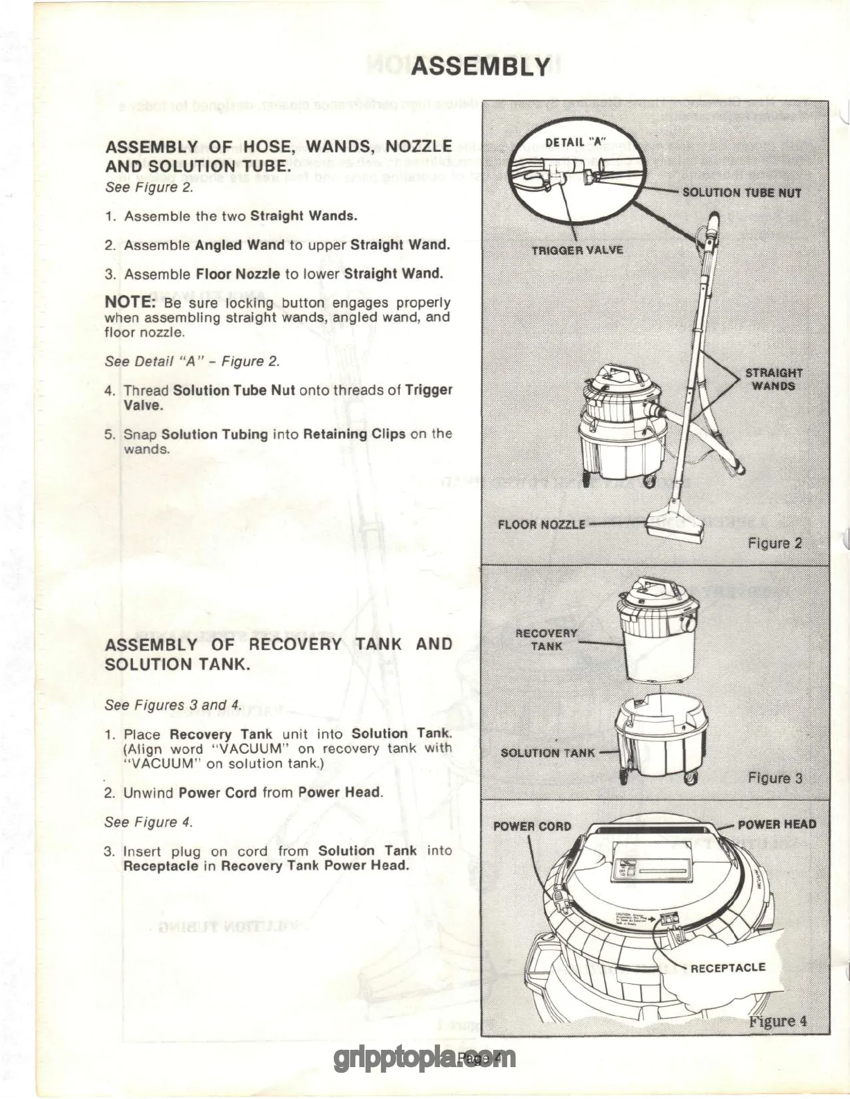
OF
HOSE, WANDS, NOZZLE
AND
SOLUTION TUBE.
See
Figure
2.
1.
Assemble
the two
Straight Wands.
2.
Assemble Angled Wand
to
upper Straight Wand.
3.
Assemble Floor Nozzle
to
lower Straight Wand.
NOTE:
Be
sure locking button engages properly
when
assembling straight wands, angled wand,
and
floor nozzle.
See
Detail
"A" -
Figure
2.
4.
Thread Solution Tube
Nut
onto threads
of
Trigger
Valve.
5.
Snap
Solution
Tubing into Retaining Clips
on the
wands.
ASSEMBLY
OF
RECOVERY TANK
AND
SOLUTION TANK.
See
Figures
3 and 4.
1.
Place
Recovery
Tank
unit into Solution
Tank.
(Align
word "VACUUM"
on
recovery tank with
"VACUUM"
on
solution tank.)
2.
Unwind
Power
Cord from
Power
Head.
See
Figure
4.
3.
Insert plug
on
cord from Solution
Tank
into
Receptacle
in
Recovery
Tank
Power
Head.
SOLUTION
TUBE
NUT
STRAIGHT
WANDS
FLOOR
NOZZLE
Figure
2
RECOVERY
TANK
SOLUTION
TANK
POWER
CORD
POWER
HEAD
Figure
4
Page
4


