3
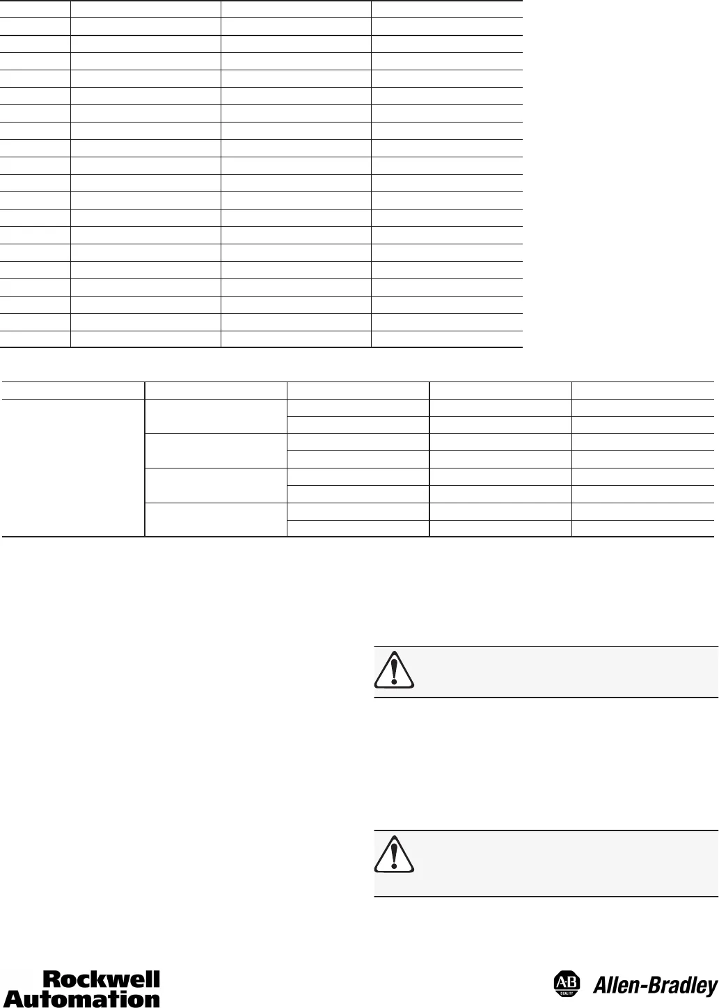
Electrical Connections—19 Pin Connector (Binary Coded Decimal)
Pin 845-CA-D-___ Wire Color 1000 BCD (12 Bit) 360 BCD (10 Bit)
V Red +DC +DC
A Brown 1 1
B Orange 2 2
C Yellow 4 4
D Green 8 8
E Blue 10 10
F Violet 20 20
G Gray 40 40
H White 80 80
J White/Orange 100 100
K White/Brown 200 200
L White/Red 400 N/C
M White/Yellow 800 N/C
N White/Green N/C N/C
P White/Blue N/C N/C
R White/Black Direction Control Direction Control
S White/Violet Reset Reset
T Black DC Common DC Common
U White/Gray Latch Control Latch Control
Electrical Connections for SSI Output—12 Pin Connector
Catalog Number Wire Pair Wire Color Function Pin
Red +DC Input 8
Red/Black/Shield
Black DC Common 1
White Clock + 3
845-CA-G-
White/Black/Shield
Black Clock - 11
__
(With 12 pin connector
Blue Data + 2
Blue/Black/Shield
Black Data - 10
Green Direction Control 12
Green/Black/Shield
Black Reset 9
Direction Pin
The Direction Pin can change function with code type. In
parallel type Gray Code encoders, its function is Most
Significant Bit Complement or MSBC for short. In Natural
Binary, Binary Coded Decimal and Gray Code SSI encoders,
its function is Direction Control.
Direction Control Ê
Natural Binary and BCD
A logic “1” (+DC or open) on the direction control pin will
produce increasing counts with a counterclockwise rotation of
the shaft. A logic “0” (DC common) on the direction control pin
will produce increasing counts with a clockwise rotation of the
shaft.
Gray Code (SSI)
A logic “1” (+DC or open) on the direction control pin will
produce increasing counts with a clockwise rotation of the
shaft. A logic “0” (DC common) on the direction control pin will
produce increasing counts with a counterclockwise rotation of
the shaft.
Ê Rotation is viewed from the end of the encoder shaft.
Gray Code (parallel)
Counterclockwise rotation of the shaft will produce increasing
counts. For increasing counts with a clockwise rotation, use
the Most Significant Bit Complement Pin instead of the Most
Significant Bit Pin. See Electrical Connection table for pin
designation.
ATTENTION: For parallel gray code: connecting the
MSB or MSBC to +DC will result in permanent
damage to the encoder.
Reset Pin
The shaft must be stationary before using the reset function.
Connecting the Reset Pin to +DC will reset Natural Binary and
BCD position value to zero. Connecting the Reset Pin to +DC
will reset Gray Code position value to zero if MSB is used or
to maximum, (e.g., 255, 511, 1023, etc.) if MSBC is used. The
reset function requires a connection to +DC for 0.1 seconds or
longer.
ATTENTION: Activating the Reset Pin results in a
change of position reading. This can cause
unexpected motion which could result in damage to
the product, equipment, or personal injury.


