Bulletin 814S - 10000099363 (version 02) http://www.ab.com/en/epub/catalogs/12768/229240/229258/3170949/10357727/ 8021099
4 Mechanical mounting
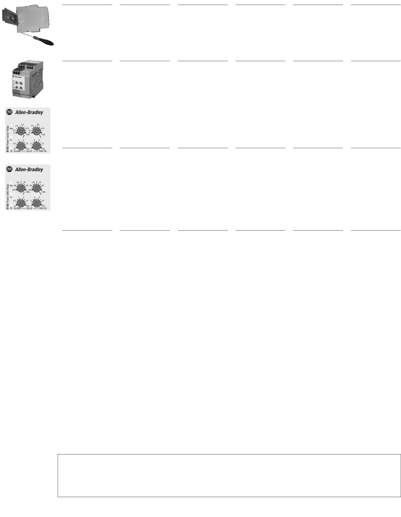
Hang the device to the DIN-
rail being sure that the
spring closes. Use a screw-
driver to remove the product
as shown in figure.
5 Startup and adjustment
Check if the current input
range is correct. Turn the
power supply ON.
The green LED is ON.
Adjust the upper and lower
levels on the absolute scale
setting the left and right
centre knobs respectively.
Adjust the alarm and power
ON delay setting the right
and left lower knob.
See datasheet for the work-
ing mode explanation.
6
I
mportant
S
hould you require infor-
m
ation about installation,
o
peration or maintenance
of the product that is not
covered in this instruction
document, contact your
local Rockwell Automation
sales office or Allen-
Bradley distributor. The
information in this docu-
m
ent is not considered
b
inding on any product
f
amily.
7 T
erminals
3-Phase power supply
1-Phase power supply
(short cir
cuit L2, L3 or 6, 7)
C
urrent input (Dir
ect or
s
tandard CT)
Latch/Inhibit (SW3 OFF) or
Start/Stop (SW3 ON) contact
Relay output
Each terminal can accept up
to 2 x 2.5 mm
2
wir
es.
(30-14 A
WG, stranded or
solid).
4 Montage mécanique
Accrocher l'appareil au rail
DIN et s'assurer que le res-
sort se referme bien. Pour
déposer l'appareil, utiliser
un tournevis comme illustré
sur la figure.
5 Démarrage et réglage
Vérifier que la gamme du
courant d'entrée est correc-
te. Mettre l'alimentation
sous tension.
La LED verte s'allume.
Régler les niveaux supérieur
et inférieur sur l’échelle, en
agissant respectivement sur
les boutons gauche et droit.
Régler l'alarme et le temps
de mise sous tension en
agissant respectivement sur
les boutons gauche et droit.
Se référer à la fiche techni-
que pour l'explication sur le
mode de fonctionnement.
6
Important
Si vous désirez des infor-
mations sur l'installation,
fonctionnement ou la main-
tenance du produit qui ne
sont pas couvertes dans ce
d
ocument d'instructions,
v
euillez communiquer avec
v
otre bureau local Rockwell
A
utomation ou le distribu-
t
eur Allen-Bradley. Les
informations contenues
dans ce document ne sont
pas considérées comme
obligatoires pour toute la
famille de produits.
7 Bornes
Alimentation triphasée
Alimentation monophasée
(court circuit L2, L3 or 6, 7)
Courant d'entrée (Continu
ou TC standard)
Contact de mémorisation/
interdiction (SW3 désactivé)
ou démarrage/arrêt (SW3
activé) relais de sortie activé
Relais de sortie
Chaque borne accepte jus-
qu'à deux conducteurs de
2,5 mm
2
.
(30-14 AWG, bloqué ou
solide).
4 Montaje mecánico
Colocar el equipo en el car-
ril DIN, asegurándose que el
muelle cierra. Utilizar un
destornillador para
desprender el equipo como
se indica.
5 Puesta en marcha y ajuste
Comprobar que la escala de
entrada de intensidad es
correcta. Conectar el equi-
po.
El LED verde se ilumina.
Ajustar los niveles superior
e inferior sobra la escala
con los potenciómetros
superiores izquierdo y dere-
cho respectivamente.
Ajustar la alarma y el retardo
de la alimentación con los
potenciómetros inferiores
derecho e izquierdo.
Véase su hoja de datos para
la explicación del modo de
operación
6
Importante
S
i necesita informaciónes
s
obre la instalación, modo
de operación o manteni-
miento del producto que no
estan cubiertas en este
documento de instruccio-
nes, póngase en contacto
con su oficina local de ven-
tas Rockwell Automation o
e
l distribuidor de Allen-
B
radley. Las informaciónes
c
ontenidas en este docu-
mento no se consideran
obligatorias para toda fami-
lia de productos.
7 Terminales
Alimentación trifásica
Alimentación monofásica
(cortocircuitar L2, L3 o 6 y 7)
Entrada de intensidad (direc-
ta o con trafo estándar)
Salida de relé de contacto:
Enclavar/Inhibir (SW3 OFF) o
Arranque/Parada (SW3 ON)
Salida de relé
Cada terminal acepta cables
de hasta 2 x 2,5 mm
2
.
(30-14 AWG, varados o sóli-
dos).
4 Montaggio sulla guida DIN
Agganciare lo strumento alla
guida DIN verificando la
chiusura della molla. Per
rimuovere il prodotto dalla
guida usare un cacciavite
come mostrato in figura.
5 Accensione e regolazione
Controllare che la gamma
della corrente di ingresso
sia corretta. Alimentare lo
strumento. Il LED verde si
accende.
Impostare le soglie minima e
massima sulla scala agen-
do sulle manopole centrali
di sinistra e destra rispetti-
vamente.
Impostare il ritardo all’inser-
zione e all’avvio agendo
sulle manopole in basso di
destra e sinistra rispettiva-
mente.
Vedere datasheet per il
modo di funzionamanto
6
Importante
Per informazioni su installa-
zione, funzionamento o
manutenzione del prodotto
che non sono contemplate
n
el presente foglio istruzio-
n
i, contattare il locale uffi-
c
io commerciale Rockwell
Automation o il distributore
Allen-Bradley. Le informa-
zioni contenute in questo
documento, per ogni fami-
glia di prodotti, non sono
considerate vincolanti.
7 Terminali di collegamento
Alimentazione trifase
Alimentazione monofase
(collegare L2 e L3 o 6 e 7)
Ingresso in corrente (Inserz.
diretta o TA standard)
Ingresso di Latch/Inibiz.
(SW3 OFF) o Start/Stop
(SW3 ON)
Uscita relè
Ad ogni morsetto possono
essere collegati 2 fili di
2,5 mm
2
.
(30-14 AWG, flessibile o rigi-
do).
4 Mekanisk montering
Når enheden monteres på
DIN-skinnen, skal det sikres,
at fjederen lukker. Brug en
skruetrækker til at fjerne
produktet som vist på illu-
strationen.
5 Opstart og justering
Kontrollér, at indgangsstrø-
mområdet er korrekt. Tænd
for strømforsyningen.
Den grønne lysdiode er
TÆNDT.
Indstil værdierne for øvre og
nedre nivau på skalæn ved
at indstille midterste knap i
henholdsvis venstre og
højre side.
Juster alarm- og indkobling-
sforsinkelsen ved at indstille
nederste knap i højre og
venstre side.
Se datablad for beskrivelse
af funktion.
6
Vigtigt
Skulle du kræve
oplysninger om installation,
funktionsbeskrivelse eller
vedligeholdelse af produk-
t
et, som ikke er omfattet af
d
enne instruktion doku-
m
ent, skal du kontakte dit
lokale Rockwell
Automation salgskontor
eller Allen-Bradley distrib-
utør. Oplysningerne i dette
dokument ikke betragtes
som bindende for ethvert
produkt familie.
7 Terminaler
3-faset forsyningsspænding
1-faset forsyningsspænding
(kortslut L2, L3 eller 6, 7)
Indgangsstrøm (dir
ekte eller
standar
d-strømmåletran-
sformator)
Selvholde/spærr
e-kontakt
(SW3 deaktiver
et) eller
start/stop-kontakt (SW3
aktiver
et)
Relæstyret udgang
Hver klemme er klassificeret til
ledninger på op til 2 x 2,5mm
2
.
(30-14 AWG, strandede eller
fast).
4 M
ontage
Hängen Sie das Relais in die
DIN-Schiene ein;
achten Sie darauf, daß die
Feder bei der Befestigung
einrastet. Verwenden Sie
einen Schraubendreher,
um das Relais wieder aus-
zubauen, wie im nebenste-
henden Bild gezeigt.
5
Einschalten und
Einstellungen
Prüfen Sie, ob der
Eingangsstrombereich rich-
tig gewählt ist. Schalten Sie
die Betriebsspannung EIN.
Die grüne LED leuchtet.
Stellen Sie den oberen bzw.
unteren Grenzwert mit dem
linken bzw. rechten mittleren
Drehknopf auf der Skala ein.
Stellen Sie Alarmverzögerung
und Einschaltverzögerung
mit dem rechten und dem
linken unteren Drehknopf
ein.
Erklärung zur Arbeitsweise
siehe Datenblatt
6
Wichtig
S
ollten Sie Informationen
ü
ber Installation, Betriebs-
a
rten oder Wartung des
P
rodukts, die nicht in die-
ser Installationshinweise
a/jointfilesconvert/1605347/bgedeckt sind, wenden
Sie sich zu Ihrem lokalen
Rockwell Automation-
Vertriebsbüro oder Allen-
Bradley-Distributor. Die
Informationen in diesem
Dokument sind nicht ver-
b
indlich für jedes Produkt
F
amilie.
7 Anschlußklemmen
Betriebsspannung
Drehstrom-Netz
Betriebsspannung
1-Phasennetz
(L2, L3 oder 6,7 überbrücken)
Stromeingang (Direkt oder
über Standardwandler)
Kontakt für Selbsthalten/
Sperren (SW3 AUS) oder
Start/Stop (SW3 EIN)
Relaisausgang
Kelemmenanschluß bis max.
2 x 2,5 mm
2
je Klemme.
(30-14 AWG, flexibel oder
starr).
L1, L2, L3
L1, L2
I1, I2
Z1, U1
15, 16, 18
“UL notes”
•
For Canadian application, these devices shall be supplied by a secondary circuit, which is not directly derived from the primary circuit and where the short-circuit limit between conductors or
between conductors and gr
ound is 1500 VA or less: the short-circuit volt ampere limit is the product of the open circuit voltage and the short circuit ampere. For other applications additional
consideration shall be evaluated in the final use.
•
“Use 60 or 75°C copper (CU) conductor and wire size No. 30-14 AWG, stranded or solid”.
• “Terminal tightening torque of 4.4 Lb-In”.
• Being these devices Overvoltage Category III they are: "For use in a circuit where devices or system, including filters or air gaps, are used to control overvoltages at the maximum rated
impulse withstand voltage peak of 6 .0 kV. Devices or system shall be evaluated using the requirements in the Standard for Transient Voltage Surge Suppressors, UL 1449 and shall also with-
stand the available short circuit current in accordance with UL 1449".
814S-PF3
814S-W3


