SafeShield Safety Light Curtain Hardware User Manual
36
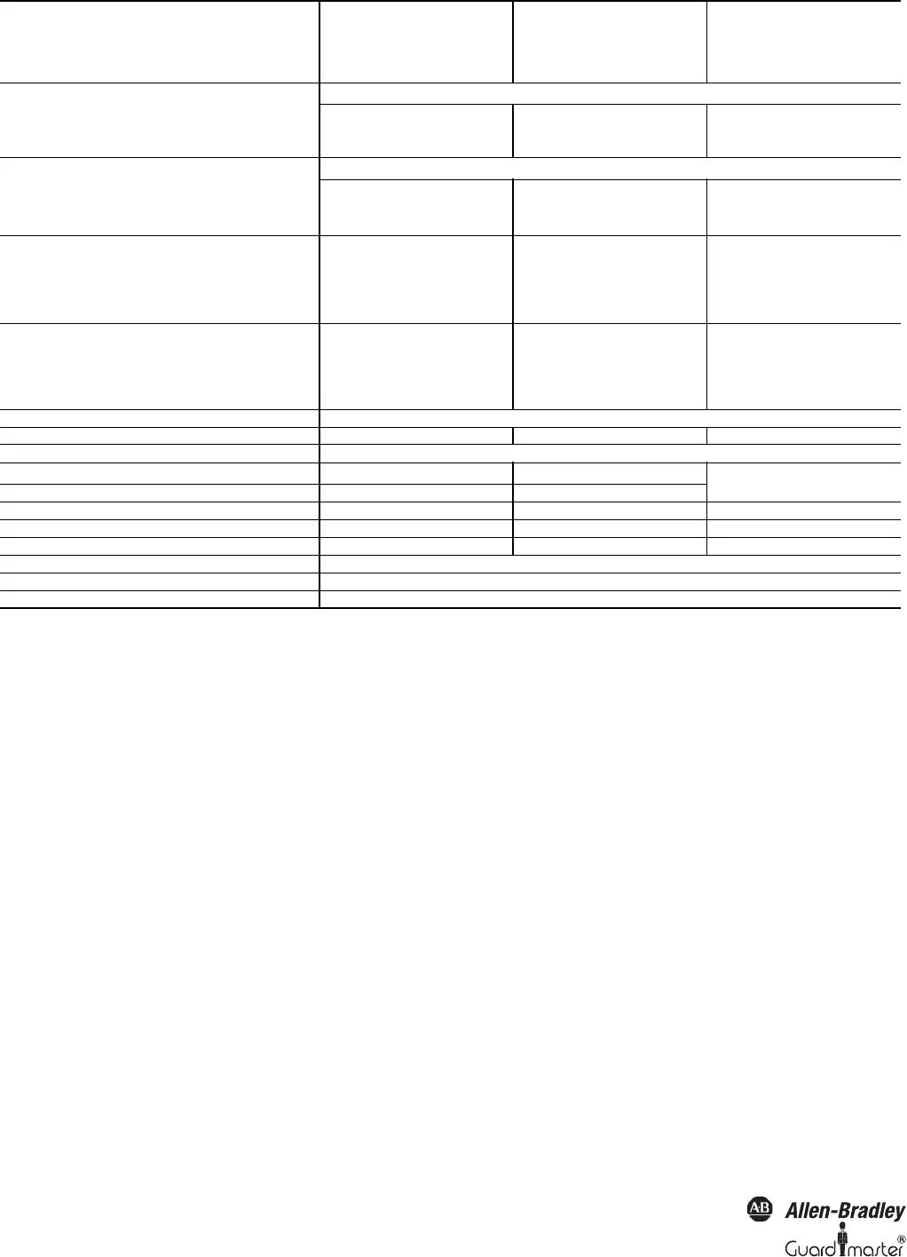
Table 24: Technical data SafeShield safety light curtain
Input voltage
11)
LOW (inactive)
–30V 0V 5V
Input current LOW –2.5mA 0mA 0.5mA
Operation time control switch input 200ms
Output Reset required
PNP semiconductors, short-circuit protected
12)
24V lamp output 4 W/0.2 A
Switching voltage HIGH (active) 15V 24V 28.8V
Switching voltage LOW (inactive) High resistance
Signal output (ADO)
PNP semiconductors, short-circuit protected
12)
Switching voltage HIGH (active) U
V
- 4.2V 24V U
V
Switching voltage LOW (inactive) High resistance
Switching current 0mA 100mA
Emergency stop
Changeover time 2s
Latency time 200ms
Cable resistance 30 Ω
Cable capacitance 10 nF
Teach-in key-operated switch/ switch for deactivating
the blanking
Cable resistance 30 Ω
Cable capacitance 10 nF
Operation time (reset button) 240ms
Weight Depending on protective field height (see page 38
Operating data
Connection M23 metal body connector
Cable length
13)
50m
Wire cross-section 0.75mm²
Ambient operating temperature 0°C (32°F) +55°C (131°F)
Air humidity (non-dewing) 15% 95%
Storage temperature –25°C (13°F) +70°C (158°F)
Housing cross-section 40mm × 48mm
Rigidity 5g, 10-55Hz acc. to IEC 60_068-2-6
Shock resistance 10g, 16ms acc. to IEC 60_068-2-29
1. The external voltage supply must be capable of buffering brief mains failures of 20 ms as specified in EN 60204-1. Suitable power supplies are available as
accessories from Rockwell Automation.
2. Within the limits of U
V
.
3. As per IEC 61131-2.
4. Applies to the voltage range between –30V and +30V.
5. As per IEC 61131-2.
6. On the device plug.
7. In the case of a fault (0-V cable open circuit) the max. leakage current flows in the OSSD cable. The downstream controller must detect this status as
LOW. A FPLC (Fail-safe Programmable Logic Controller) must be able to identify this status.
8. The maximum rated load inductance is higher with lower switching sequence.
9. When active, the outputs are tested cyclically (brief LOW). When selecting the downstream controllers, make sure that the test pulses do not result in
deactivation when using the above parameters.
10.
0
Make sure to limit the individual line core resistance to the downstream controller to this value to ensure that a short-circuit between the outputs is
safely detected. (Also note EN 60204 Electrical Machine Equipment, Part 1: General Requirements.)
11.
1)
As per IEC 61131-2.
12.
2)
Applies to the voltage range between –30V and +30V.
13. Depending on load, power supply and wire cross-section. The technical specifications must be observed.
Minimum Typical Maximum


