160_5_9DU2.doc 2 Mon Sep 15 11:42:00 1997
2 160 SSC™ Variable Speed Controller (Series B)
General Instructions for an
EMC Compliant Installation
Refer to Figure 1.
Shielded Enclosure
• Typical NEMA or IEC metal enclosures are adequate.
• The ground connection of the shielded enclosure must be solidly
connected to the PE terminal of the controller. Good conductivity
must be assured – grounding must provide a low impedance path
to high frequency signals.
• All wiring, except input power leads, must use shielded cable.
• Input power, output power and control wiring inside the enclosure
must be physically separated.
• Input power, output power and control wiring outside the enclosure
must use separate shielded cables, or separate conduit.
Cable Clamps
• Use suitable EMC-tested cable clamps only.
• The connection area must be 360 degrees around the shielded cable.
• The cable clamps also provide strain-relief for the cable.
• When using conduit, the contact point of metal entry connections
must be free of paint or non-conductive surfaces and solidly
connected with good conductivity to the enclosure.
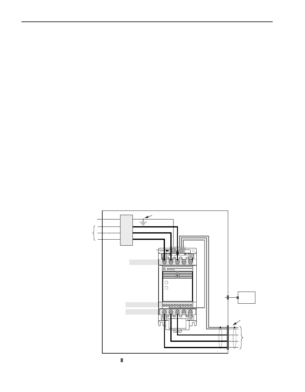
Figure 1 Recommended Grounding Configuration
R (L1)
S (L2)
T (L3)
PE
AC
Input Line
Shielded Enclosure
Enclosure Ground Connection
U (T1)
Shielded Motor Cable
to TB3
Control
Cabinet
*
to Motor
V (T2)
W (T3)
R (L1)
S (L2)
T (L3)
= EMC Tested Shielded Cable Clamp (or Metal Conduit)
* When the control circuitry is located outside of the 160 enclosure.
Control Wiring TB3
Motor Wiring TB2
L2
S
L1
R
L3
T
BR
–
BR
+
1 2 3 4 5 6 7 8 9 10 11
T2
V
TI
U
T3
W
–
DC
+
DC
Ground Tab – PE
Line Power TB1
FAULT
READY
Line
Filter


