INSTALLATION
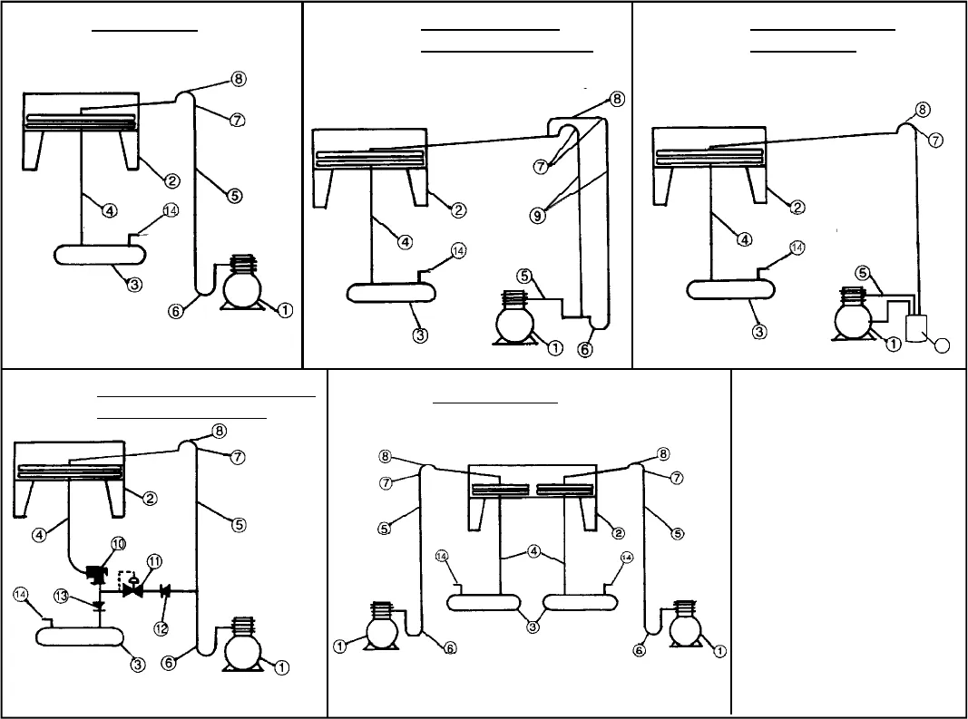
Figure 3 - Single Circuit
Figure 4(a) - Single circuit with
double discharge riser
(may be required with
capacity control)
Figure 5 - Single circuit regulator valve
head pressure control
Figure 6 - Multiple circuits
LEGEND
1 - Compressor
2 - Air Cooled Condenser
3 - Receiver
4 - Condensate Line
5 - Discharge Line
6 - Trap-minimum 18” (157 mm)
7 - Reverse Trap-minimum
6” (152 mm)
8 - Access Schrader Valve
9 - Double Discharge Riser
10 - Head Pressure Regulator
(open on rise of inlet)
11 - Receiver Pressure Regulator
Valve (opens on rise of
differential)
12 - Check Valve “A”
13 - Check Valve “B”
14 - Receiver Relief Valve
15 - Oil Separator
ELECTRICAL WIRING
All wiring and connections to the air cooled condenser
must be made in accordance with the National Electrical
Code and all local codes and regulations. Any wiring
diagrams shown are basic and do not necessarily
include electrical components which must be field
supplied. (see pages 8-11 for typical wiring diagrams).
Refer to the Electrical Specifications table on pages 5, 15
and 19 for voltage availability and entering service
requirements.
SYSTEM START-UP CHECKS
1. Check the electrical characteristics of all components
to be sure they agree with the power supply.
2. Check tightness of all fans and motor mounts.
3. Check tightness of all electrical connections.
4. Upon start-up, check fans for correct rotation. Air is
drawn through the condenser coil. To change rotation
on 3 phase units reverse any two (2) fan motor leads.
5. All system piping must be thoroughly leak checked
before a refrigerant charge is introduced.
- 37 -
BVC TYPICAL SYSTEM PIPING
Fig. 3 - 6
MAINTENANCE
A semi annual inspection should be carried out by a
qualified refrigeration service mechanic. The main power
supply must be disconnected.
1. Check electrical components. Tighten any loose
connections.
2. Check control capillary tubes and lines for signs of wear
due to excessive vibration or rubbing on metal parts.
Secure if necessary.
3. Check tightness of all fans and motor mounts. Remove
any deposits which could effect fan balance. Note: Fan
motors are permanently lubricated and require only
visual inspection.
4. Clean the condenser coil using a soft brush or by
flushing with cool water or coil cleansers available
through NRP (National Refrigeration Products Inc.)
5. Update service log information (back page of service
manual)
Figure 4(b) - Single circuit with
Oil Separator (may be
required with capacity
control)
15


