- 9 -
APPLICATION
These Unit Coolers are designed for use with R12,
R22, R134a, R404A, R407A/B/C, R507 or R502
refrigerants.
At room temperatures above 34°F and evaporating
temps no lower than 27°F the air flowing through the
coil will accomplish the defrost. Temperatures of 34°F
and below (to -40°F) require positive defrosting.
(either Electric or Hot Gas).These models require the
use of (1) Time Clock (to initiate and terminate the
defrost cycle). (2) Fan-Delay thermostat (to prevent
evaporator fans from starting up right after defrost and
blowing water on to fan blades, guards and floor) (3)
Defrost Termination Control (to prevent unnecessary
prolonged heating and steaming of the coil once all
the ice and frost has melted).
The coil must not be exposed to any abnormal atmos-
pheric or acidic environments. This may result in
corrosion to the cabinet and possible coil failure
(leaks). (Consult manufacturer for optional baked on
phenolic protective coatings).
INSTALLATION
The installation and start-up of Unit Coolers should
only be performed by qualified refrigeration mechan-
ics.
This equipment should be installed in accordance
with all applicable codes, ordinances and local by-
laws.
INSPECTION
Inspect all equipment before unpacking for visible
signs of damage or loss. Check shipping list against
material received to ensure shipment is complete.
IMPORTANT: Remember, you, the consignee, must
make any claim necessary against the transportation
company. Shipping damage or missing parts, when
discovered at the outset, will prevent later unneces-
sary and costly delays.
If damage or loss during transport is evident,
make claim to carrier, as this will be their respon-
sibility, not the manufacturer’s.
Should carton be damaged, but damage to equip-
ment is not obvious, a claim should be filed for “con-
cealed damage” with the carrier.
IMPORTANT: The electrical characteristics of the unit
should be checked at this time to make sure they
correspond to those ordered and to electrical power
available at the job site.
Save all shipping papers, tags and instruction sheets
for reference by installer and owner.
LOCATION
The unit location in the room should be selected to
ensure uniform air distribution throughout the entire
space to be refrigerated. Be sure that the unit does
not draw air in, or blow directly out, through an
opened door and that the product does not obstruct
the free circulation of air. Allow a minimum of 24”
clearance at each end and behind the unit.
The Unit Coolers draw air through the coil and dis-
charge air from the fan side.
Consideration should be given to the coil location in
order to minimize the piping run length to the con-
densing unit and floor drain.
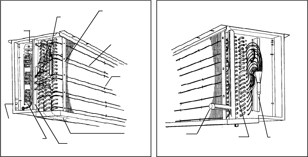
ELECTRICAL VIEW
PIPING VIEW
ADJUSTABLE DEFROST
TERMINATION
CONTROL
DEFROST
THERMOSTAT
BULB
REAR HEATER SLOT
COVER PLATE
(REMOVE 5 SCREWS)
DRAIN PAN
HEATER
ELEMENT(1)
TERMINAL BLOCKS
DEFROST CONTROL (TOP)
HEATERS (MIDDLE)
FAN MOTORS (BOTTOM)
ENTERING
SERVICE
KNOCK-OUTS
FRONT HEATER
SLOT COVER PLATE
(REMOVE 5 SCREWS)
HEATER
SPRING
CLIPS
DEFROST HEATER
ELEMENTS (6)
(4 0N AIR-ENTERING SIDE,
2 ON LEAVING AIR-SIDE)
TX VALVE
CONNECTION
EXTERNAL
EQUALIZER
CONNECTION
SUCTION
CONNECTION


