Northwinds Blast Chiller Operations Manual 2013 © Bally Refrigerated Boxes, Inc. 16
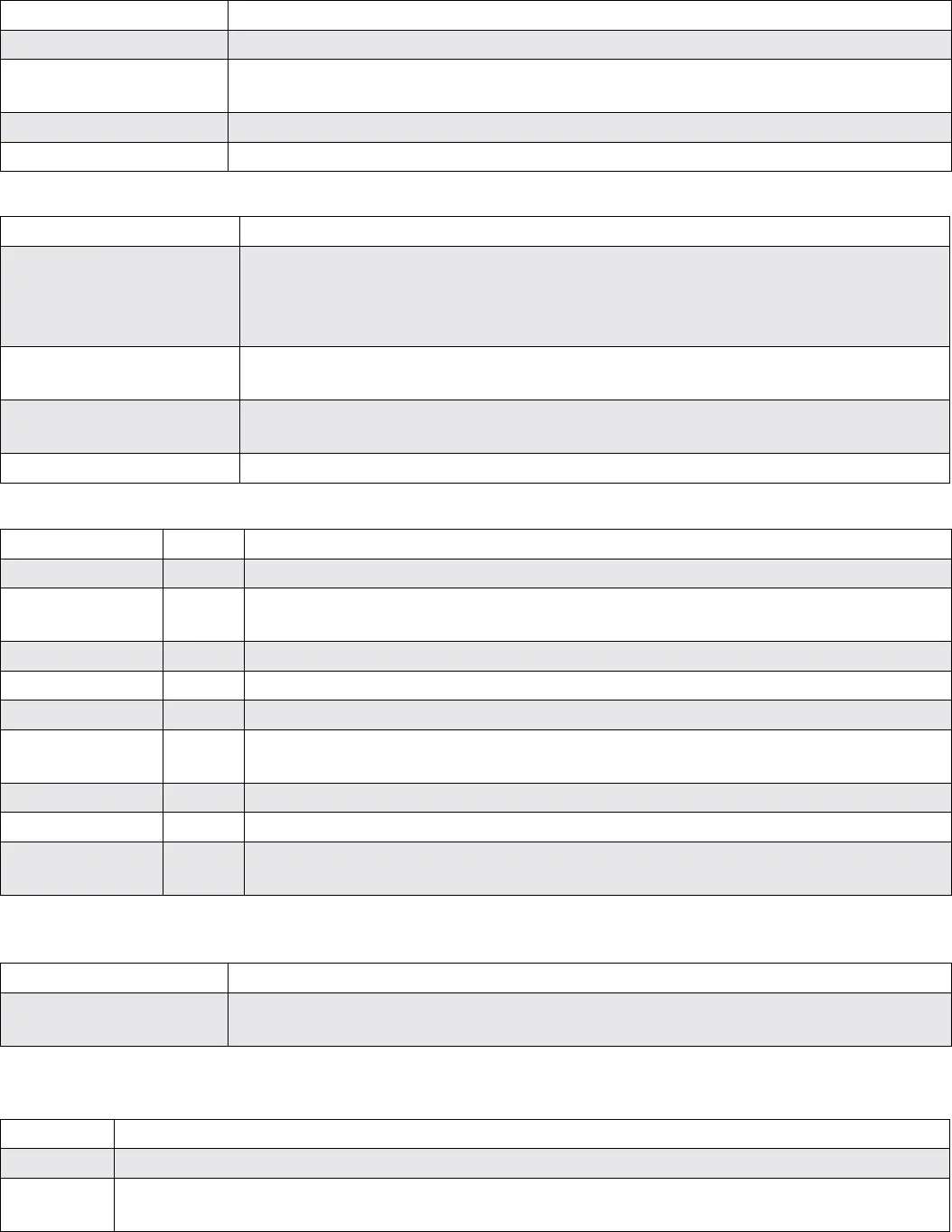
Screen Reads Appears When
Measured Temperatures: Show temperatures for the Air, Product, and Auxiliary Probes.
Manual Mode Time Set the time for the manual cycle to run by following instructions on the screen. Any
time changes take eect immediately.
Refrigeration Status: This is an on/o indicator
Fault Page Indicates if there are any faults (such as broken thermocouple circuits).
10. The Display Screens in Manual Mode:
Manual Mode: Air temperature in large letters on the top line, followed by the total chill time in small letters, and the
current time (Time since chilling started). As you push the down arrow, you will see the following screens in this order:
11. The Red Light: When there is a critical failure a red operational error light and an alarm turns on. Possible triggers are:
Error displayed on screen Meaning
Air temperature above 100° This is most likely due to a refrigeration failure. The unit will shut down so that the fans
will not draw out even more heat from the food, perhaps triggering the re suppression
system. The food must be cooled some other way, and the refrigeration system must be
serviced.
Fan contactor failure This is a self-diagnosis by the controller. The fans will not come on if the fan contactor
fails. Any food must be cooled elsewhere, and replace the contactor.
Defrost contactor failure This is self-diagnosis by the controller. The unit will not defrost. This may not prevent
acceptable performance, since it only eects defrost. Replace the contactor.
Air probe open The air temperature input probe is not working correctly, and the unit cannot operate.
Item Part# Location/Means of Access
Fan Motor 016915 Inside Fan Frame/Remove entire Fan Cover (not the wire fan guards).
Refrigeration Valve 005424 Part of the Liquid Line, left side of Coil Frame. Unscrew the 6 black topped screws, and
remove coil lter and side cover.
Solenoid Valve 061514 Attached to the Refrigeration Valve. Part of the Liquid Line. (See above).
TXV 000388 Part of the Liquid Line (See above).
Power Head 099644 Attached to TXV, above (Special 60” bulb tube).
Defrost Switch 088779 In the top bend of coil frame, usually on the Liquid Line side. (Wired closely to the coil
junction box.)
Air Probe 046759 Behind the upper fan motor. Remove the Fan Cover (not the Wire guard).
Auxiliary Probe 089226 In plain sight. Plugged into top of coil frame.
Light Bulb none In plenum. Unscrew 4 at head screws with a 2.5mm hex key (not a common size). Hex
key is taped to the light at the time of shipment.
Problem Solution
Erroneous probe readings Use a light abrasive pad (like Scotch-Brite) to clean the plugs, and a Q-tip to clean the
receptacles.
Problem Symptom
Fails Closed The Defrost Cycle cannot be initiated. Even when the coil is frozen solid
Fails Open The full 20 minute Defrost Cycle will occur after every Chilling cycle. Even when the blast chiller interior
is at room temperature.
12. Item Maintenance Locations for Bally Northwinds Blast Chillers
Probe plugs: The temperature probes are low voltage circuits that are routed through plugs located at the top of the
coil frame and behind the fan frame.
Defrost Switch: The defrost switch sends a signal back to the controller indicating the temperature of the coil. The
switch is designed to handle high amperages and has a life span of about 100,000 cycles.


