3
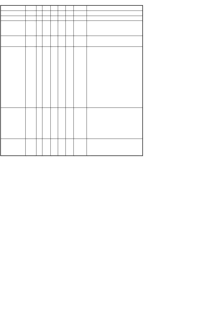
Model Number Chart
Display
The EDA has two displays: a lower larger display and a smaller upper display. The Home Display is the normal dis-
play while the control is in operation if there are no errors or functions active. The Home display will indicate the
process variable at the current condition with the lower display and the selected pressure units for the process vari-
able with the upper display. When programming the unit both displays are also used. The Programming Chart in this
instruction manual indicates what both displays show while programming the unit. For programming descriptions in
this instruction manual the format used is “lower display – upper display”. For example Ctrl – 1SP shows that Ctrl
would be in the lower display and 1SP would be in the upper display.
When the user presses the E key to edit an item’s value the upper display will flash “EDIT” and the lower display will
blink. When the user presses the E key to then save the edit to the value the upper display will flash “SAVE” and
the lower display will stop blinking.
Example
S
eries
H
ousing
P
rocess
Connection
Electrical
Connection
R
ange
Transmitter
Output
Options
E
DA
E
DA
W
N
1
B
1
A1
E1
0
1
02
03
04
05
0
6
0
7
08
09
10
11*
12*
T0
T1
T2
T3
T4
T5
STW
NIST
23444
EDAW-N1E1-01T0-SST
Electronic Pressure Controller
W
eatherproof
1
/4˝ NPT male bottom
1
/4˝ BSPT male bottom
7/16˝ SAE male bottom
Two 1/2˝ female NPT
conduit connections
0 – 30” Hg vacuum
0 – 20 psi
0 – 60 psi
0 – 100 psi
0
– 150 psi
0
– 300 psi
0
– 600 psi
0 – 1000 psi
0 – 1500 psi
0 – 3000 psi
0 – 6000 psi
0 – 8000 psi
None
4 to 20 mA
1 to 5 VDC
0 to 5 VDC
1 to 6 VDC
0 to 10 VDC
Stainless Steel Tag
NIST Certificate
Special Cleaning
*Not UL listed.


