©Copyright 2009 Dwyer Instruments, Inc. Printed in U.S.A. 4/09 FR# R1-443716-00
MAINTENANCE
Routine inspection is not required except for periodic inspection of the
cable and molding to ensure that these are neither damaged nor softened
by incompatible liquid. A periodic check of the zero and span settings is
also recommended. Otherwise these transmitters are not field serviceable
and should be returned to the factory if repair is needed. Be sure to include
a brief description of the problem plus any pertinent application information
available.
DWYER INSTRUMENTS, INC.
Phone: 219/879-8000 www.dwyer-inst.com
P.O. BOX 373 • MICHIGAN CITY, INDIANA 46361, U.S.A. Fax: 219/872-9057 e-mail: info@dwyer-inst.com
MOUNTING
The pressure transducer is designed to be attached by the coupling
thread, and can be mounted in any plane or direction. To tighten the fit, use
a 5/8 UNF AF (M16) wrench on the hexagon provided and apply a
maximum torque of 20 lb-ft (27 N-m). The customer must assure that the
pressure seal is suitable for the application.
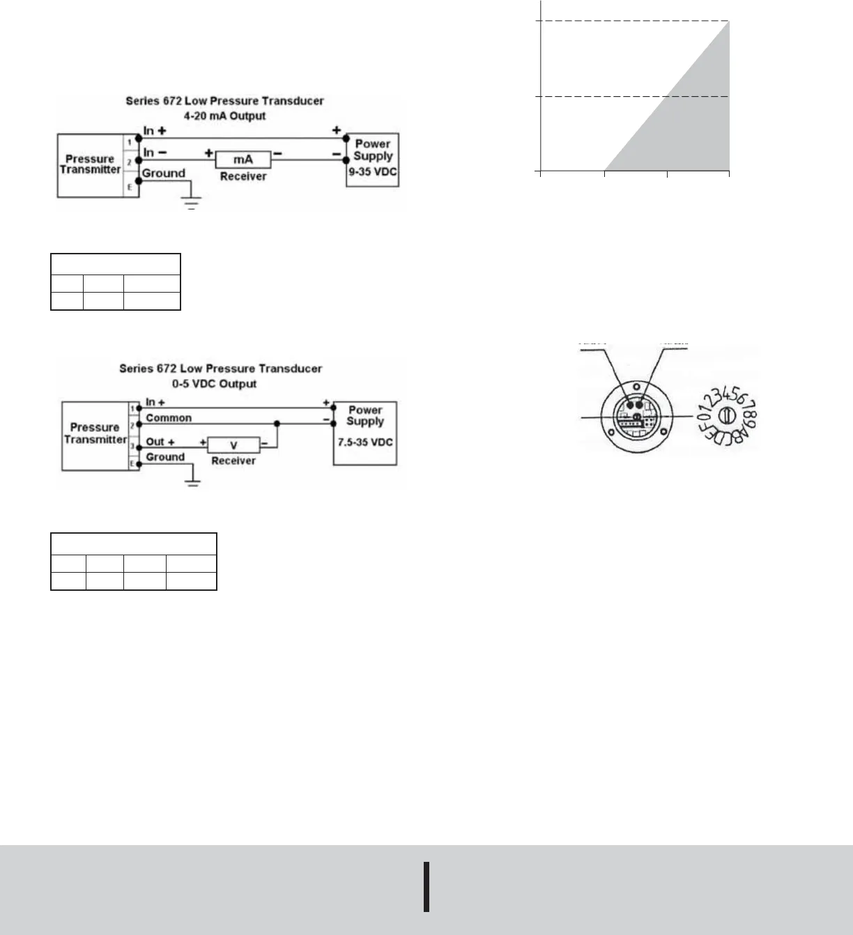
ELECTRICAL
Electrical Connections:
Electrical connections are made by way of a DIN 43650 connector with
mating plug.
Load Resistance (4-20 mA Transducer)
The total permissible resistive load in the loop (to include all cable
resistance) can be from zero to (50x supply voltage – 9) ohms, e.g. with a
12 VDC supply, the permissible load is from zero up to 150 ohms.
ZERO/SPAN ADJUSTMENT
Zero and span controls are precisely set during manufacturing and should
only need adjustment if there is a change in the required pressure
measurement. Inquire with Dwyer Instruments, Inc. before adjustment.
R
LOOP
1
MAX = 50 (V
SUPP
-9)
1325
575
0
0
9
20
35
TOTAL RESISTANCE
(OHMS)
SUPPLY VOLTAGE
(VDC)
ZERO
SPAN
RANGE SWITCH
4-20 mA Output
ln+
1
ln-
2
Ground
E
0-5 VDC Output
ln+
1
Com
2
Out+
3
Ground
E
A-30-672:TEMPLATE 4/9/09 11:15 AM Page 2


