4. Position: The transmitter is not position sensitive. However, all standard models
are originally calibrated with the unit in a position with the pressure connection
downward. Although they can be used at other angles, for best accuracy it is
recommended that units be installed in the position calibrated at the factory.
ELECTRICAL INSTALLATION
1. Electrical Connections: The 644 is available with cable version or bayonet
connector options having different connector pin outs shown in table below:
2. Voltage Output Units
The Series 644 voltage units are four-wire type circuit with 0 to 10 VDC analog output.
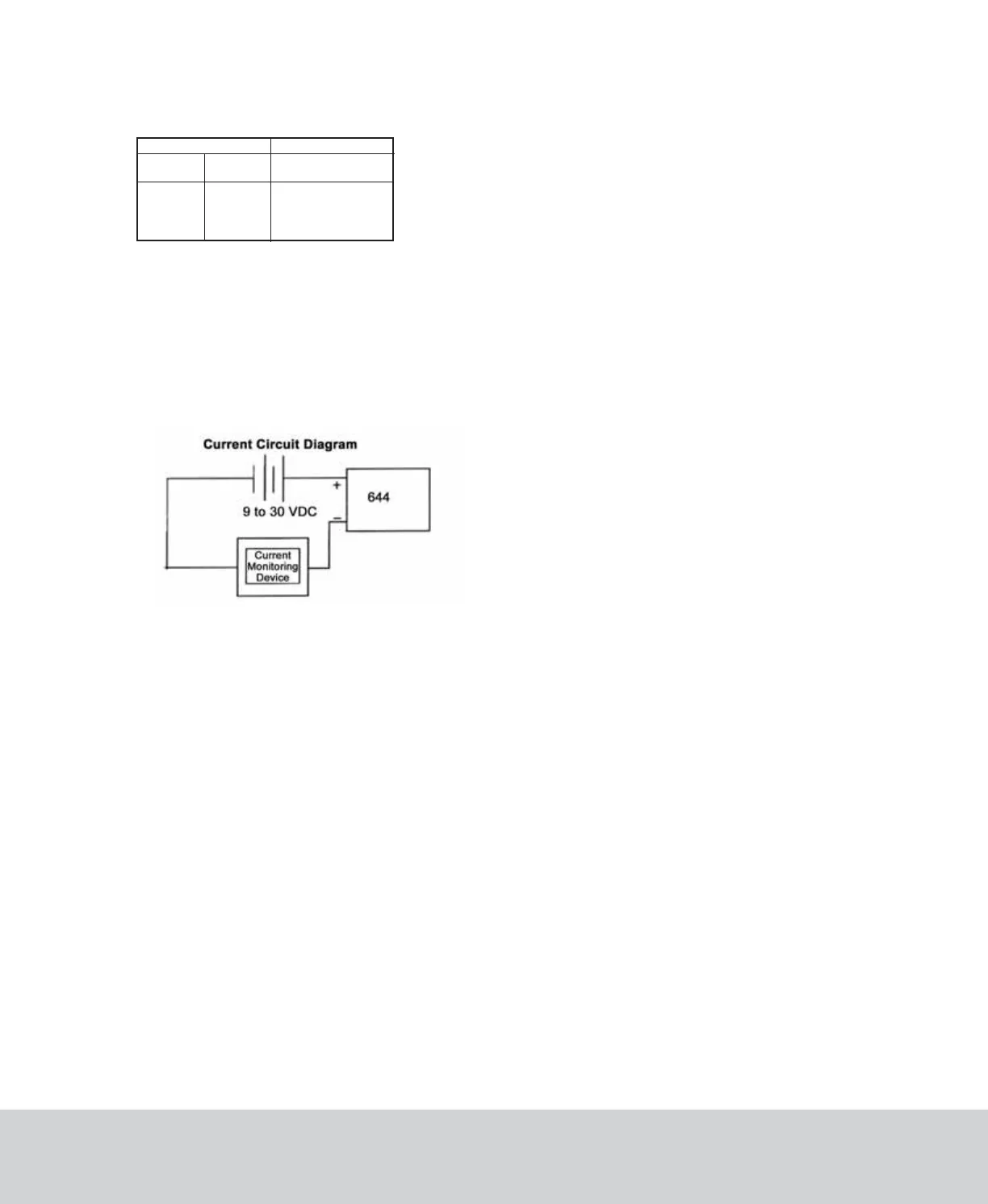
3. Current Output Units
The Series 644 current units are two-wire loop-powered 4 to 20 mA current output and
delivers rated current into any external load of 0 to 800 ohms.
The current flows into the + terminal and returns back to the power supply through the
- terminal (see Diagram 1). The power supply must be a DC voltage source with a
voltage range between 9 and 30 measured between the + and - terminals. The unit is
calibrated at the factory with a 24 VDC loop supply voltage and a 250 ohm load.
Diagram 1
MAINTENANCE
After final installation of the pressure transmitter and its companion receiver, no
routine maintenance is required. A periodic check of system calibration is suggested.
The Series 644 transmitter is not field repairable and should be returned if repair is
needed (field repair should not be attempted and may void warranty). Be sure to
include a brief description of the problem plus any relevant application notes. Contact
customer service to receive a return goods authorization number before shipping.
DWYER INSTRUMENTS, INC.
Phone: 219/879-8000 www.dwyer-inst.com
P.O. BOX 373 • MICHIGAN CITY, INDIANA 46361, U.S.A.
Fax: 219/872-9057
e-mail:
[email protected]©Copyright 2010 Dwyer Instruments, Inc. Printed in U.S.A. 11/10 FR# RA-443867-00
Wiring Codes
Electrical
Connection
+ EXC
- EXC
+ Sig Out
- Sig Out
Code-B
Cable Wire
Color
Red
Black
Green
White
Bayonet
Connector Pinout
A
D
B
C
P-644:SSS-1000 11/4/10 2:21 PM Page 2


