-11
Introduction
Optional lenses
Lens Projection distance for 100" screen size
Wide-zoom lens ( 1.5 – 1.9) AN-C12MZ 10' 5" – 13' 1" (3.2 m – 4.0 m)
Tele-zoom lens ( 2.2 – 2.8) AN-C18MZ 15' 7" – 19' 10" (4.8 m – 6.0 m)
Tele-zoom lens ( 3.3 – 5.1) AN-C27MZ 23' 2" – 35' 8" (7.1 m – 10.9 m)
Tele-zoom lens ( 5.1 – 7.2) AN-C41MZ 36' 2" – 50' 10" (11.0 m – 15.5 m)
The standard zoom lens is attached to the projector.
The optional lenses from Sharp are also available for specialized application. Please see
y our nearest Sharp Authorized Projector Dealer for details on all the lenses. (Refer to the
SETUP MANUAL on the supplied CD-ROM f or details.) Also, be sure to have service person-
nel install the optional lenses.
Throw Distance
The graph below is for 100 inches (254 cm) screen with 16:10 Signal Input (Normal Mode).
Screen
10 20 30 5040 55(ft)
Downloaded From projector-manual.com Sharp Manuals
-17
Quick Start
Pages 31, 32
4. Adjust the angle
5. Adjust the focus and the zoom
7. Tu rn the Power off
Page 30
6. Select the INPUT mode
Page 34
This projector is equipped with an ÒAuto V-Keystone
CorrectionÓ function that automatically corrects any
trapezoidal distortion within the projected image.
Bring the projected image into focus
Bring the projected image into focus by
rotating the focus ring.
Adjust the projected image size
Adjust the projected image size by moving the
zoom knob.
Select the ÒCOMPUTER 1Ó using the INPUT buttons on the projector or the COMPUTER 1 button on the remote control.
When you press the INPUT buttons on the projector, the INPUT list appears.
Press
''
''
' /
""
""
" to select an item on the list, and press ENTER to switch to the selected INPUT mode.
When using the remote control, press COMPUTER1 /2, DVI , S-VIDEO or VIDEO to
switch the INPUT mode.
On the remote
control
On the
projector
""
""
" INPUT list
Press the STANDBY button, then press that button again while the confirmation message is displa yed, to put the projector into s tandby mode.
Even if you unplug the power cord from the AC outlet, the cooling fan continues to run for a while.
On the remote controlOn the projector
""
""
" On-screen Display
Adjust the projector angle
Adjust the projector angle using the Height
Adjustment buttons.
Rotate the Tilt dial to adjust the horizontal tilt of
the projector.
Height Adjustment
buttons
Tilt dial
Focus ring
Zoom knob
Zoom in
Zoom out
""
""
" On-screen Display (RGB)
RGB
1024 768
COMPUTER1
INPUT
COMPUTER1
COMPUTER2
D VI-D Computer
D
Page 33
Downloaded From projector-manual.com Sharp Manuals
-23
Connections
Connecting to a Computer
Before connecting, ensure the power cord of the projector from the AC outlet is unplugged,
and that the devices to be connected are turned off . After making all connections, turn on the
projector and then the other devices. When connecting a computer, ensure that it is the last
device to be turned on after all the connections are made.
Ensure the operation manuals of the devices to be connected have been read before making connections.
When connecting with the RGB cable
(Connecting to COMPUTER/COMPONENT 1 or 2: The illustration shown below is for the former.)
To audio output terminal
To RGB output terminal
* ø3.5 mm stereo or mono audio cable
(commercially available or available as Sharp service part QCNWGA038WJPZ)
To COMPUTER/
COMPONENT 1
input terminal
Computer
To AUDIO input terminal
RGB cable
*
When using the ¿3.5 mm mono audio cable, the volume level will be half of when using the ¿3.5 mm stereo audio cable.
Note
See page 65 ÒComputer Compatibility ChartÓ for a list of computer signals compatible with the projector.
Use with computer signals other than those listed may cause some of the functions to not work.
A Macintosh adaptor may be required for use with some Macintosh computers. Contact your nearest
Macintosh Dealer.
Depending on the computer y ou are using, an ima ge ma y not be pr ojected unless the computerÕs
external output port is switched on. (e .g. Press ÒFnÓ and ÒF5Ó keys simultaneously when using a
SHARP notebook computer). Refer to the specific instructions in your computerÕs operation manual to
enable your computerÕs external output port.
RGB cable
Supplied
accessory
Downloaded From projector-manual.com Sharp Manuals
-25
Connections
Connecting to Video Equipment
The image quality is highest in order of the Component signal, the RGB signal, the S-video signal and the
Video signal. If your audio-visual equipment has a component output terminal or RGB output terminal, use the
COMPUTER/COMPONENT terminal 1 or 2 on the projector for video connection.
When connecting video equipment with a DVI output terminal
Note
Select the input signal type of the video equipment. See page 47.
While the projector is connected to video equipment that has an HDMI output terminal, only the video
signal can be input to the projector. (Connect the AUDIO input terminal for audio input.)
Depending on specifications of video equipment or HDMI to DVI digital cable, the signal transmission
may not work property. (The HDMI specification does not support all connections to video equipment
that has HDMI digital output terminal using HDMI to DVI digital cable.)
For details on compatibility for connection, see support information on DVI connection provided by the
video equipment manufacturer.
When connecting video equipment with component video output terminal
(Connecting to COMPUTER/COMPONENT 1 or 2: The illustration shown below is for the former.)
Note
When you connect video equipment with a 21-pin RGB output (Euro-scart) to the projector, use a
commercially available cable that fits in the projector terminal you want to connect.
The projector does not support RGBC signals via the Euro-scart.
DVI Digital cable (commercially available)
To audio output terminals
ø3.5 mm stereo minijack to RCA audio cable
(commercially available)
To DVI output terminal
Video Equipment
To DVI-D
input terminal
To AUDIO input terminal
(for COMPUTER/COMPONENT 2, DVI-D)
To audio output terminal
ø3.5 mm minijack to RCA audio cable (commercially available)
3 RCA (Component) to 15-pin D-sub cable
(optional: AN-C3CP2)
To component video output terminal
To COMPUTER/COMPONENT 1
input terminal
To AUDIO
input terminal
Video Equipment
Downloaded From projector-manual.com Sharp Manuals
-41
Useful Features
ÒScreen adjustment (SCR-ADJ)Ó menu
On
Off
On
Off
Main Menu Sub Menu
OSD Display
Background
Logo
Blue
None
Normal
Full
Dot By Dot
Area Zoom
V-Stretch
Stretch
Center
Upper Right
Lower Right
Upper Left
Lower Left
Menu Position
Page 50
Resize
Page 49
Page 50
Page 50
Auto V-Keystone
Page 49
Page 49
Page 49
+40-40
Image Shift
V-Keystone
Page 49
+100-100
H-Keystone
SCR-ADJ
Page 49
Language
Page 50
Front
Ceiling + Front
Rear
Ceiling + Rear
PRJ Mode
Page 50
English
Deutsch
Espa–ol
Nederlands
Fran•ais
Italiano
Svenska
Portugu•s
polski
Magyar
TŸrk•e
+60-60
ÒSignal adjustment (SIG-ADJ)Ó menu
On
Off
SIG-ADJ
+30-30
+60-60
+150-150
+150-150
Clock
Phase
H-Pos
V-Pos
Reset
Signal Info
Resolution
Main Menu
Auto Sync
Page 47
Page 47
Page 47
Page 47
Page 48
*4
*4
*5
*5
*5
Signal Type
Page 47
Page 48
*6
Auto
RGB
Component
Dynamic Range
*7
Auto
Standard
Enhanced
Auto
PAL
SECAM
NTSC4.43
NTSC3.58
PAL-M
PAL-N
PAL-60
Video System
Page 48
*8
*4 Item when inputting RGB signal through COMPUTER/COMPONENT 1 or 2
*5 Item when inputting COMPUTER/COMPONENT 1 or 2
*6 Item when selecting COMPUTER/COMPONENT 1, 2 or DVI-D
*7 Item when selecting DVI-D
*8 Item when selecting VIDEO or S-VIDEO
Downloaded From projector-manual.com Sharp Manuals
-47
Useful Features
0
0
0
0
Phase
Clock
Pict. SIG
Ð
ADJ SCR PRJ Net.
H-Pos
V-Pos
Reset
Auto
640 x 480
On
Standard
Auto
SEL./ADJ.
RETURN
ENTER
END
Resolution
Auto Sync
Signal Type
Dynamic Range
Video System
Signal Info : 800 x 600
H 60.3 kHz / V 37.8 Hz
1
3
4
5
6
2
7
Signal Adjustment (ÒSIG-ADJÓ Menu)
11
11
1
Adjusting the Computer Image
If the optimum image cannot be obtained with Auto
Sync adjustment, use the SIG-ADJ function.
ENTER
22
22
2
Resolution Setting
Ordinarily, the type of input signal is detected and the
correct resolution mode is automatically selected. How-
ever, for some signals, the optimal resolution mode in
Ò ResolutionÓ on the Ò SIG-ADJÓ menu may need to be
selected to match the computer display mode.
48
33
33
3
Auto Sync Adjustment
Used to automatically adjust a computer image.
AUTO SYNC
Menu operation
Page 43
44
44
4
Signal T ype Setting
This function allows you to select the input sig-
nal type RGB or Component for COMPUTER/
COMPONENT 1, 2 or DVI-D.
Downloaded From projector-manual.com Sharp Manuals
-49
Useful Features
Resize
0
0
0
Image Shift
H-Keystone
V-Keystone
Auto V-Keystone
Center
On
On
Normal
Logo
Front
English
SEL./ADJ.
RETURN
ENTER
END
OSD Display
Background
Menu Position
PRJ Mode
Language
Pict. SIG SCR-ADJ PRJ Net.
1
3
4
5
6
7
8
2
Screen Adjustment (ÒSCR-ADJÓ Menu)
Menu operation
Page 43
11
11
1
Setting the Resize Mode
37
38
RESIZE
37
22
22
2
Adjusting the Image Position
You can move the projected image vertically.
37 38
button
button
33
33
3
Keystone Correction
When the image is projected either from the top or from
the bottom towards the screen at an angle, the image be-
comes distorted trapezoidally. The function for correct-
ing trapezoidal distortion is called Keystone Correction.
Set ÒAuto V-KeystoneÓ on the ÒSCR-ADJÓ screen
menu to ÒOnÓ.
Set ÒAuto V-KeystoneÓ on the ÒSCR-ADJÓ screen
menu to ÒOffÓ. Select ÒV-KeystoneÓ, and then
press or to parallelize the left and right sides
of the projected image with the slide bar. To
parallelize the upper and lower sides, select ÒH-
KeystoneÓ and press or .
Horizontal Keystone Correction
Vertical Keystone Correction
Downloaded From projector-manual.com Sharp Manuals
-51
Useful Features
Auto Power Off
Auto Restart
System Sound
Speaker
Audio Out
9600bps
Enable
On
On
On
FAO
On
Enable
Normal
Disable
SEL./ADJ.
RETURN
ENTER
END
Monitor Out
LAN/RS232C
RS-232C
Fan Mode
System Lock
All reset
Lamp Timer (Life) [ 0]h [ 0] min ( 100%)
Pict. SIG SCR PRJ-ADJ Net.
1
2
3
4
5
6
7
8
9
0
q
w
Menu operation
Page 43
Description
The projector automatically enters the
standby mode when no input signal is
detected for 15 minutes or longer.
The Auto Power Off function will be
disabled.
Selectable items
On
Off
Auto Power Off Function
Note
When the Auto Power Off function is set to On,
5 minutes before the projector enters the
standby mode, the message Enter STANDBY
mode in X min. will appear on the screen to
indicate the remaining minutes.
Description
If the power cord is unplugged from the
outlet or the breaker switch is turned off
when the projector is on, then the
projector automatically turns on when
the power cord is plugged into the AC
outlet or the breaker switch is turned on.
The projector does not turn on auto-
matically when the power cord is
plugged into the AC outlet or the
breaker switch is turned on.
Selectable items
On
Off
22
22
2 Auto Restart Function
Description
A confirmation sound is made when the
projector turns on/off.
No confirmation sound is made.
Selectable items
On
Off
Setting the Confirmation
Sound (System Sound)
Helpful Functions Set during Installation (Ò PRJ-ADJ Ó menu)
Speaker Setting
This function allows you to set the audio output
of the internal speaker to ÒOnÓ or ÒOffÓ such as
when the projector is connected to an external
amplifier.
Selectable items
On
Off
Description
The audio signal is output from the internal
speaker.
The audio signal is not output from the
internal speaker.
Audio Output Type Setting
This function determines whether the audio level
output from the A UDIO output (MONIT OR output)
terminal is fixed or variable by linking with VOL-
UME.
Info
When Audio Out has been set to VAO, first make
sure to lower the volume of the projector before
turning the power on or off and when switching the
input.
Description
A udio output that does not vary in
strength with the volume level of the
source projector.
A udio output that varies in strength with
the volume level of the source projector.
Selectable items
FAO
(Fixed Audio
Output)
VAO
(Variable
A udio Output)
Monitor Output
LAN/RS232C
When set to ÒEnableÓ, the function is activated
and power is consumed even in the standby mode.
It is recommended that the function be set to ÒDis-
ableÓ when it is not connected. This reduces power
consumption when the projector is in the standb y
mode.
Description
The function is activated even if the
projector is in standby mode.
The function is switched off when the
projector is in standby mode.
Selectable items
Enable
Disable
Note
When you want to control the projector using
the LAN/RS232C function, select Enable.
Downloaded From projector-manual.com Sharp Manuals
-53
Useful Features
Menu operation
Page 43
5
Enter the same keycode in ÒRe-con-
firmÓ.
Note
To cancel the keycode that you have al-
ready set
Press " on the projector for four times in steps
4 and 5 above.
When the System Lock is set
When System Lock is set, the keycode input screen
appears after the power is turned on. When it ap-
pears, enter the right keycode to start projection.
Input screen for keycode
Info
Keylock cannot be set while the projector is: dis-
playing the ÒMenuÓ screens, in standby mode,
warming up, changing input signals, operating
ÒAuto SyncÓ function or on the ÒSystem LockÓ
screen during warming up.
System Lock
ÐÐÐÐ
Keylock Function
Locking the Operation Buttons on
the Projector
Use this function to lock the operation but-
tons on the projector.
Locking the Operation Buttons
Hold down on the projector for about 5 sec-
onds while the projector is being turned on.
On-screen Display
Keylock function ON
The keylock function does not affect the operation
with the remote control buttons.
You cannot use the keylock function while the pro-
jector is warming up.
Taking the Keylock off
Hold down on the projector for about 5 seconds.
On-screen Display
Keylock function OFF
When the projector is in standby mode, you can
release the keylock by holding down and
on the projector simultaneously for
about 5 seconds.
Returning to the Default
Settings
This function allows you to initialize the settings
y ou have made in the projector.
Note
The following items or menu cannot be initialized.
ÒSIG-ADJÓ menu
Resolution
ÒSCR-ADJÓ menu
Language
ÒPRJ-ADJÓ menu
Lamp Timer (Life)
System Lock
Checking the Lamp Life
Status
You can confirm the cumulative lamp usa ge time
and the remaining lamp life (percentage).
Note
It is recommended that the lamp be changed
when the remaining lamp life becomes 5%.
Remaining lamp life changes within the range
of the values shown depending on the frequency
at which ÒEco+Quiet ModeÓ is switched to ÒOnÓ
and ÒOffÓ. (See page 46.)
The lamp life may vary depending on the us-
age condition.
Lamp usage condition
ÒLifeÓ
Operated exclusively
while ÒEco+Quiet ModeÓ
is ÒOnÓ.
Operated exclusively
while ÒEco+Quiet ModeÓ
is ÒOffÓ.
Remaining lamp life
100% 5%
Approx. Approx.
3,000 hours 150 hours
Approx. Approx.
2,000 hours 100 hours
Downloaded From projector-manual.com Sharp Manuals
-63
Appendix
User service screw
(for lamp unit cover)
AC socket
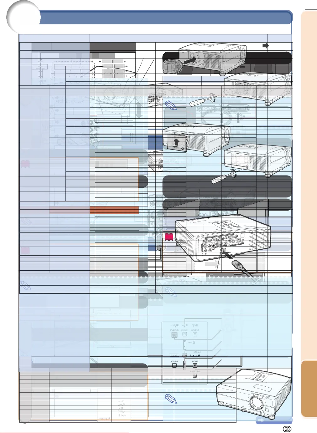
5 Insert the new lamp unit.
Press the lamp unit firmly into the lamp
unit compartment. Fasten the securing
screws.
6 Replace the lamp unit cover.
Align the lamp unit cover and slide it to
close. Then tighten the user service
screw to secure the lamp unit cover.
Info
If the lamp unit and lamp unit cover are not
correctly installed, the power will not turn
on, even if the power cord is connected to
the projector.
Resetting the Lamp Timer
Reset the lamp timer after replacing the lamp.
Info
Make sure to reset the lamp timer only
when replacing the lamp. If you reset the
lamp timer and continue to use the same
lamp, this may cause the lamp to become
damaged or explode.
You can also reset the lamp timer via the
LAN.
(Refer to the SETUP MANUAL on the sup-
plied CD-ROM for details.)
1 Connect the power cord.
Plug the power cord into the AC socket
of the projector.
2 Reset the lamp timer.
While simultaneously holding down ,
ENTER and MENU on the projector,
press STANDBY/ON on the projector and
keep all four buttons pressed down until
the lamp indicator starts blinking green.
“LAMP 0000H” is displayed, indicating
that the lamp timer is reset.
button
ENTER button
STANDBY/ON button
Lamp indicator
MENU button
Downloaded From projector-manual.com Sharp Manuals
-65
Appendix
Note
This projector may not be able to display images from notebook computers in simultaneous (CRT/LCD)
mode. Should this occur, turn off the LCD display on the notebook computer and output the display data
in ÒCRT onlyÓ mode. Details on how to change display modes can be found in your notebook computerÕs
operation manual.
When this projector receives 640 350 VESA format VGA signals, Ò640 400Ó appears on the screen.
When projecting the RGB interlace signal using COMPUTER/COMPONENT 1, 2 or DVI-D with ÒSignal TypeÓ
set to ÒAutoÓ or ÒRGBÓ, the image may not be projected as desired. In this case, use either Video or S-Video.
Depending on the computer you are using, the output signal may not be faithful to the ÒScreen resolutionÓ
adjustment. Check the settings of the computerÕs signal output. If the settings cannot be changed, it is recom-
mended that the resolution be set to the one that corresponds to Ò 1280 800Ó.
Computer Compatibility Chart
Multiple signal support
Horizontal Frequency: 15Ð110 kHz
Ver tical Frequency: 43Ð85 Hz
DTV
Computer
Pixel Clock: 12Ð170 MHz
Sync signal: Compatible with TTL level
Compatible with sync on green signal
Mode Resolution VESA
Vertical Frequency
(Hz)
Analog RGB
Support
Digital RGB
Support
Horizontal Frequency
(kHz)
VGA
SVGA
XGA
WXGA
SXGA
SXGA+
UXGA
MAC 13"
MAC 16"
MAC 19"
MAC 21"
640 350
640 400
720 350
720 400
640 480
800 600
1024 768
1280 720
1280 768
1280 800
1360 768
1366 768
1152 864
1280 1024
1400 1050
1600 1200
640 480
832 624
1024 768
1152 870
27.0
31.5
37.9
27.0
31.5
37.9
27.0
31.5
27.0
31.5
37.9
26.2
31.5
34.7
37.9
37.5
43.3
31.3
35.2
37.9
46.6
48.1
46.9
53.7
40.3
48.4
56.5
60.0
68.7
45.0
47.8
49.7
62.8
47.7
47.8
55.0
66.2
67.5
64.0
80.0
64.0
65.3
75.0
34.9
49.7
60.2
68.7
60
70
85
60
70
85
60
70
60
70
85
50
60
70
72
75
85
50
56
60
70
72
75
85
50
60
70
75
85
60
60
60
75
60
60
60
70
75
60
75
60
60
60
67
75
75
75
15.7
31.5
33.8
15.6
31.3
37.5
45.0
28.1
33.8
56.3
67.5
480
480P
540P
576
576P
720P
720P
1080
1080
1080P
1080P
60
60
60
50
50
50
60
50
60
50
60
Signal Vertical Frequency (Hz) DVI SupportHorizontal Frequency (kHz)
The follo wing is a list of modes that conform to VESA. Ho we ver, this pr ojector supports other signals
that are not VESA standards.
Downloaded From projector-manual.com Sharp Manuals
-67
Appendix
CheckProblem Page
An unusual sound is
occasionally heard
from the cabinet.
Maintenance
indicator illuminates or
blinks in red.
The projector cannot be
turned on or put into the
standby mode using the
STANDBY/ON button on
the projector.
Picture is green with
component input signals
(COMPUTER/
COMPONENT 1, 2, DVI-D)
.
Picture is pink (no green)
with RGB input signals
(COMPUTER/
COMPONENT 1, 2, DVI-D)
.
Picture is too bright and
whitish.
The black levels of the
image show banding or
appear faded when DVI-
D is selected.
The cooling fan
becomes noisy.
The lamp does not light
up even after the
projector turns on.
The lamp suddenly turns
off during projection.
The image sometimes
flickers.
The lamp takes a long
time to turn on.
Picture is dark.
The remote control
cannot be used.
If the picture is normal, the sound is due to cabinet shrinkage
caused by room temperature changes. This will not affect
operation or performance.
See ÒMaintenance IndicatorsÓ.
The keylock is set.
If the keylock is set to ON, all the buttons are locked.
Change the input signal type setting.
Image adjustments are incorrectly set.
Select the Dynamic Range setting (ÒStandardÓ or ÒEnhancedÓ)
that results in the best picture quality.
When temperature inside the projector increases, the cooling
fan runs faster.
The lamp indicator is illuminating in red.
Replace the lamp.
Cables incorrectly connected to the projector or the connected
equipment works improperly.
If this happens frequently, replace the lamp.
The lamp will eventually need to be changed.
The lamp has reached the end of its life. Replace the lamp.
Operate the remote control while pointing it at the projectorÕs
remote control sensor.
The remote control may be too far away from the projector.
If direct sunlight or a strong fluorescent light is shining on the
projectorÕs remote control sensor, place the projector where it
will not be affected by strong light.
The batteries may be depleted or inserted incorrectly. Make
sure the batteries are inserted correctly or insert new ones.
Ñ
59
53
47
45
48
Ñ
59
23-29
62
62
15
15
This projector is equipped with a microprocessor. Its performance could be adversely affected by
incorrect operation or interference. If this should happen, unplug the projector and plug it in again
after more than 5 minutes.
Downloaded From projector-manual.com Sharp Manuals
-69
Appendix
Specifications
As a part of policy of continuous improvement, SHARP reserves the right to make design
and specification changes for product improvement without prior notice. The performance
specification figures indicated are nominal values of production units. There may be some
deviations from these values in individual units.
Model
Display devices
Resolution
Lens
Input terminals
Output terminals
Control and
communication
terminals
Speakers
Projection lamp
Rated voltage
Rated frequency
Input current
Power consumption (Standby)
Operation temperature
Cabinet
Dimensions (main body only) [W × H × D]
Weight (approx.)
F number
Zoom
Focus
DVI-D (Compatible with HDCP)
Computer/Component
(mini D-sub 15 pin)
S-Video (mini DIN 4 pin)
Video (RCA)
Audio (ø3.5 mm stereo minijack)
Audio (RCA)
Computer/Component
(mini D-sub 15 pin)
Audio (ø3.5 mm stereo minijack)
LAN (RJ-45)
USB (Type B)
RS-232C (mini DIN 9 pin)
Wired Remote
(ø3.5 mm stereo minijack)
XG-C455W/PG-C355W
0.74" LCD panel × 3
WXGA (1280 × 800)
F 1.7 – 1.9
Manual, ×1.2 (f = 28.0 – 33.6 mm)
Manual
×1
×2
×1
×1
×2
×2 (L/R)
×1
×1 (variable audio output)
×1
×1
×1
×1
2 W (Mono)
275 W
AC 100 – 240 V
50/60 Hz
3.6 A
360 W (3.4 W) with AC 100 V
345 W (4.4 W) with AC 240 V
41°F to 95°F (+5°C to +35°C)
Plastic
12
27
/
32
" × 4" × 11
1
/
64
"
(326 × 101.5 × 279.5 mm)
10.8 lbs. (4.9 kg)
Downloaded From projector-manual.com Sharp Manuals


