9
WARNING
IMPROPER CLUTCH COVER ASSEMBLY CAN RE-
SULT IN SERIOUS INJURY, AND WILL CAUSE SE-
VERE SAW DAMAGE IF UNIT IS STARTED. NEVER
START OR OPERATE SAW IF BRAKE BAND IS NOT
IN PLACE ON CLUTCH DRUM. ALWAYS CHECK
CHAIN BRAKE OPERATION AFTER REPLACING
COVER. DO NOT USE SAW IF CHAIN BRAKE DOES
NOT FUNCTION PROPERLY.
pRepaRation foR use
H
I
J
7. Turn saw over and check brake band for correct posi-
tion around clutch drum. If brake band is not in place
around drum, remove clutch cover, make sure brake is
released, and reinstall.
CAUTION!
• When starting, idling adjustment speed should be adjusted not to rotate the saw chain.
• When there is trouble with the carburetor, refer to your distributor or dealer.
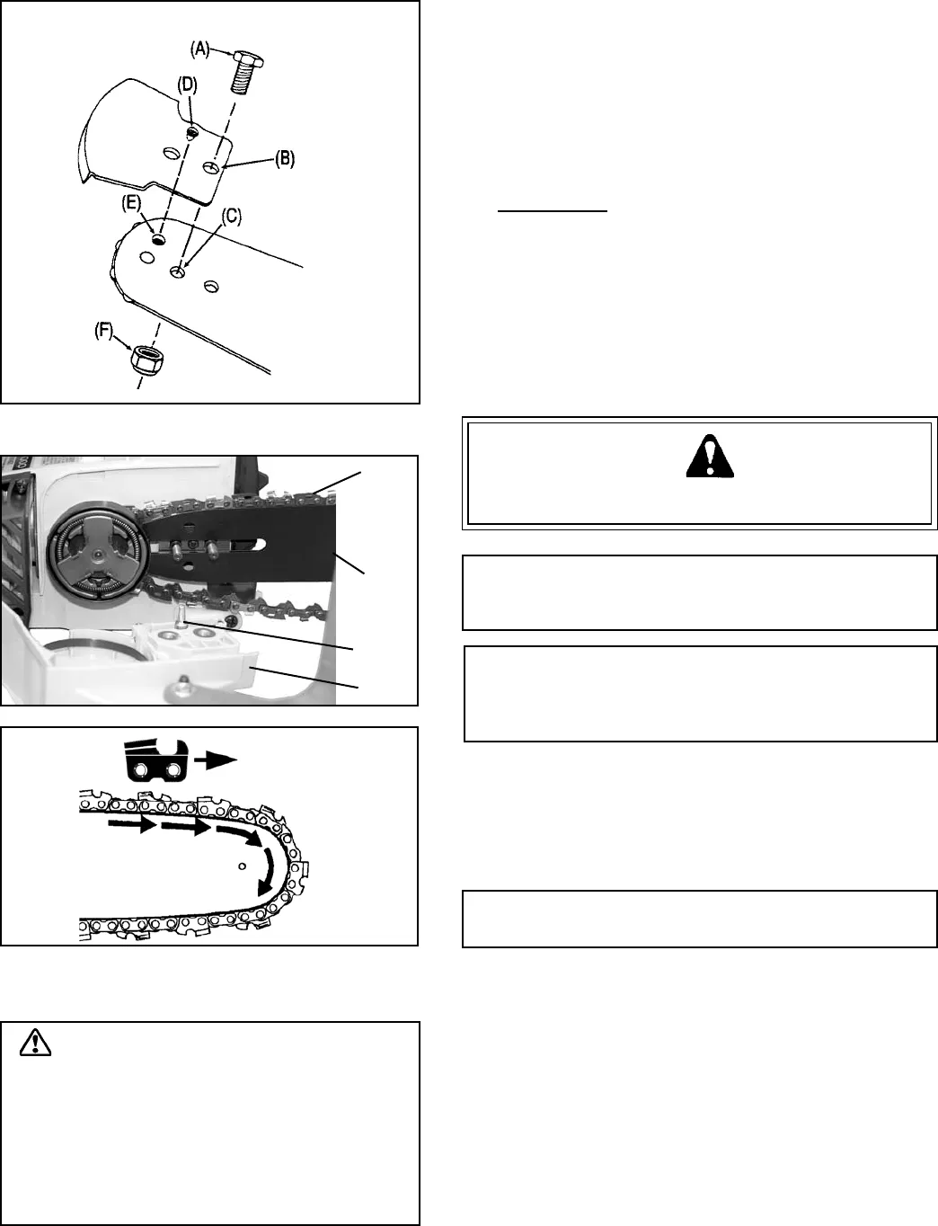
kiCk GuaRD® to baR instRuCtions
For saws with Kick Guard
®
P/N 2894901 and symmetri-
cal or asymmetrical low-kick type guide bars.
1. Install bolt (A) in rear hole (B) of Kick Guard
®
and
through front hole (C) in guide bar.
2. IMPORTANT: Dimple in Kick Guard
®
(D) must engage
recess in guide bar (E).
3. Tighten nut (F) and bolt (A) until snug. Make certain
Kick Guard
®
is ush against guide bar.
GuiDe baR anD saw Chain-install/
Remove
WARNING DANGER
Saw Chain is sharp! Always wear gloves when handling
assembly, otherwise serious personal injury may result.
NOTE
Move chain brake lever fully rearward to remove or install
clutch cover to saw.
IMPORTANT
Always loosen guide bar nuts before turning chain
tension adjuster, otherwise clutch cover and tensioner
will be damaged.
1. Remove spark plug lead.
2. Remove two guide bar nuts and remove guide bar cover.
Turn tension adjustment screw counterclockwise 2 to 3
turns if bar and chain are installed.
3. Remove guide bar and saw chain if necessary.
NOTE: See “MAINTENANCE AND CARE” instructions
for guide bar, sprocket, and saw chain maintenance.
4. Mount guide bar (G) on studs, and slide toward sprocket
to make saw chain installation easier.
5. Install saw chain (H) as shown, with cutters on top of
guide bar facing forward.
6. Align holes of clutch cover (J) with guide bar studs,
and tensioner pin (I) with lower guide bar adjuster hole.


