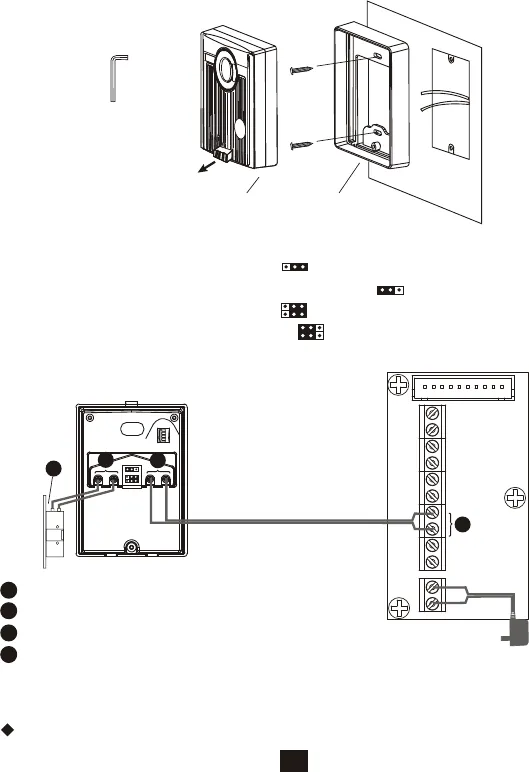
3.2. EX-700D Installation
A. Use screws wrench disassemble screw and remove door camera unit
from bracket.
B. Fasten wall mount bracket on position.
C. Fasten wires on terminals and select jumpers for desire function.
(refer to STAGE 2)
D. Mount door camera unit on bracket, secure the assembly screw.
STAGE 1: Installation door camera
Door camera Bracket
Pull out screw cover
to access the screw
STAGE 2: Wiring and setting
A. Select and plug JP2 to its RIGHT( ) to disable automatic LED light
supplement at night. Factory setting is LEFT( ) as enable.
B. Select and plug JP1 to its RIGHT( ) for direct current output control.
Factory setting has JP1 to its LEFT( ) for dry contact bridge control.
(Refer to Page 11Door Release Options)
PT1
PT2
DG1
DG2
OUT+
OUT-
DR2
DR1
POWER
<+>
<->
JP1
JP2
1
2 3 4
Main monitor
wiring terminal
Red
Black
1
EX-700D wiring terminal
2
3
4
25
Terminals for EX-700D door camera
Terminals for main monitor DR2 terminals
Terminals for door strike
Electric Lock
1
2
3
4
Operates the same as the 1st door camera unit (Refer to page 13).
3.3. EX-700D Operation
Screws wrench


