QT-80W
– 7 –
ADJUSTMENT
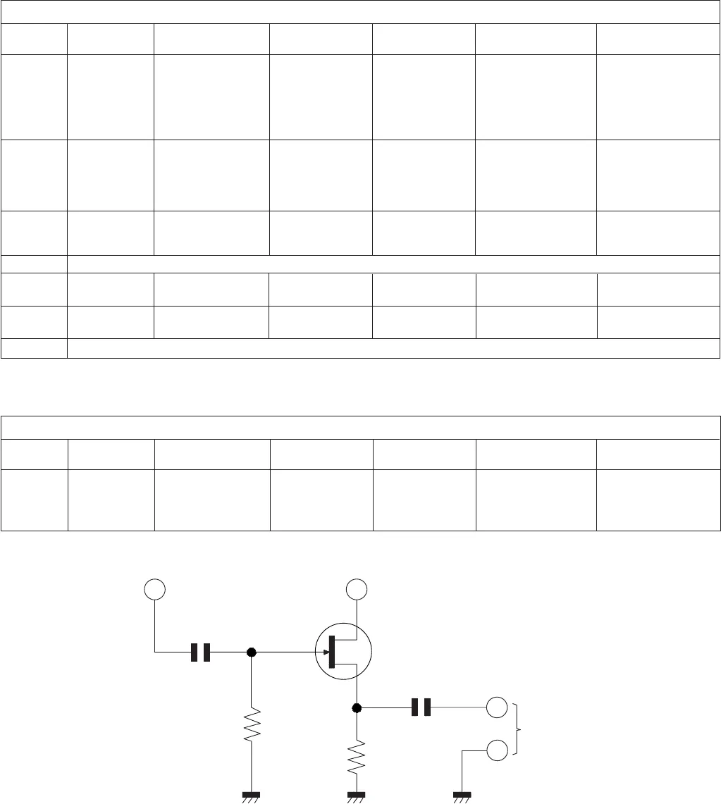
Figure 7
TUNER SECTION
fL: Low-range frequency
fH: High-range frequency
1 FM IF: (1) FM IF sweep Inject the IF Signal are taken Adjust T106, T108 (1) Band SW in FM.
10.7 MHz generator sweep signal out from point TP3 and repeat to get (2) VOL. & TONE
(T108) (2) Alignment through 300 pF best "S" curve with control in MIN.
FM oscilloscope capacitor to point center at 10.7 MHz position
DETECTION: (3) Power supply TP2 (3) Tune P.V.C. to
(T106) high end
2 FM BAND (1) FM RF sweep Inject the RF Same as step 1 Adjust P.V.C. (TC1) Same as step 1
COVERAGE fH: generator signal directly to get MAX. output
108.2 MHz (2) Alignment point TP1
oscilloscope
(3) Power supply
3 FM BAND Same as step 2 Same as step 2 Same as step 1 Adjust L103 to get Tune P.V.C. to low
COVERAGE fL: MAX. output end
87.4 MHz
4 Repeat step 2, 3 until no further improvement can be made.
5 FM TRACKING Same as step 2 Same as step 2 Same as step 1 Adjust P.V.C. (TC2) to Tune P.V.C. to
fH: 106 MHz get MAX. output 106 MHz
6 FM TRACKING Same as step 2 Same as step 2 Same as step 1 Adjust L102 to get MAX. Tune P.V.C. to
fL: 90 MHz output 90 MHz
7 Repeat step 5, 6 and then step 2, 3, 5, 6 until no further improvement can be made.
Step
Alignment
Frequency
Test Equipment
Signal-in
Signal-out
Adjust
Remark
FM Section
1 VCO: 75 kHz (1) Frequency counter Inject MONO Through test Adjust VR102 let (1) FM and stereo
(2) Power supply signal at 98 MHz circuit as Fig 7. Frequency counter position
(3) FM Signal directly to point value: 76 K ± 200 Hz. (2) Tune radio to
generator TP1 and ground 98 MHz
Step
Alignment
Frequency
Test Equipment
Signal-in Signal-out
Adjust
Remark
FM Stereo Section
Pin 13 of IC102
Pin 21 of IC102
FET 2SK212
(or other 2SK type FET)
To frequency
counter
10pF
1M ohm
10K ohm
D
G
S
0.1
F


