– 11 –
CD-E700/CD-E77
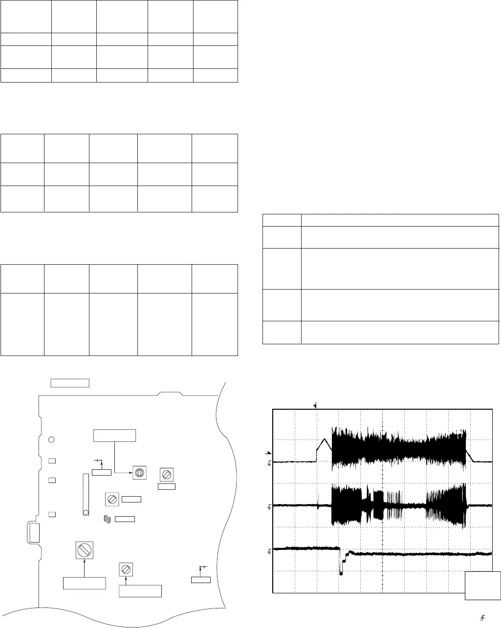
Figure 11-2
CD ERROR CODE DESCRIPTION
Error Explanation
01
When Pickup set inner position, inner switch
cannot detect 'ON' level for 10 secs.
When tray moves to Open/Close, Open/Close switch
10*
cannot detect 'ON' level for 7 secs.
When disc table rotate to target position.
Clamp switch cannot detect 'ON' level for 7 secs.
When disc table set to Disc1 position for 1 st time,
11* "CLAMP SW", "DISC NO SW" and "OPEN/CLOSE"
cannot detect 'ON' level for 14 secs.
31
When it changes to CD function, DSP cannot read
initial data.
T
T
EFBL
FDO
TE
Stopped
CH1=500 mV
DC 10:1
CH2=200 mV
DC 10:1
CH3=1 V
DC 10:1
500 ms/div
(500 ms/div)
NORM:20 kS/s
1
2
3
=Record Length=
Smoothing : ON CH1 : 0.000 V
CH2 : 0.000 V
Main : 100K
Zoom : 2k
Mode : SINGLE
Type : EDGE CH1
Delay : 0.0 ns
Hold off : 0.2 µs
CH3 : 0.00 V
CH4 : 0.00 V
BW : FULL
=Trigger==Filter= =Offset=
CH2
v/DIV
200 mV
1999/04/05 20:26:47
Test Stage Frequency Frequency
Display
Setting/
Adjusting
Parts
Instrument
Connection
CD SECTION
••
••
•
AM IF/RF
Signal generator: 400 Hz, 30%, AM modulated
*1. Input: Antenna Output: TP302
*2. Input: Antenna Output: TP301
TUNER SECTION
fL: Low-range frequency
fH: High-range frequency
AM IF 450 kHz 1,720 kHz T351 *1
AM Band — 530 kHz (fL): T306 *2
Coverage 1.1 ± 0.1 V
AM Tracking 990 kHz 990 kHz (fL): T303 *1
*1. Input: Antenna Output: TP301
*2. Input: Antenna Output: Speaker terminal
••
••
• FM RF
Signal generator: 1 kHz, 40 kHz dev., FM modulated
FM Band — 87.50 MHz T301 (fL): *1
Coverage 1.3 V ± 0.1 V
FM RF 98.00 MHz 98.00 MHz L312 *2
(10-30 dB)
Test Stage Instrument
Connection
Frequency Frequency
Display
Setting/
Adjusting
Point
Figure 11-1 ADJUSTMENT POINTS
Items adjusted automatically
(1) Offset adjustment (The offset voltage between the head
amplifier output and the VREF reference voltage is
compensated inside the IC.)
* Focus offset adjustment
* Tracking offset adjustment
(2) Tracking balance adjustment (waveform drawing
Fig.11-2 EFBL)
(3) Gain adjustment (The gain is compensated inside the IC
so that the loop gain at the gain crossover frequency will
be 0 dB.)
* Focus gain adjustment
* Tracking gain adjustment
• Adjustment
Since this CD system incorporates the following automatic
adjustment functions, readjustment is not needed when
replacing the pickup. Therefore, different PWBs and pickups
can be combined freely.
Each time a disc is changed, these adjustments are
performed automatically. Therefore, playback of each disc
can be performed under optimum conditions.
••
••
• FM IF
Signal generator: 10.7 MHz, FM modulated
IF 10.7 MHz 98 MHz T302 *1
(Turn the
core of trans-
former T302
fully counter-
clock wise)
Test Stage
Instrument
Connection
Frequency Frequency
Display
Setting/
Adjusting
Point
*1. Input: Antenna Output: TP301
AM IF
FM RF
TP301
TP302
FM IF
T301
T302
R356
T303
T306
IC301
L312
T351
CNP301
AM/FM LOOP
ANTENNA
FM BAND
COVERAGE fL
AM BAND
COVERAGE fL
AM TRACKING
fL
MAIN PWB
1
R381
* 'CHECKING'
If Error is detected, 'CHECKING' will be display instead of 'ER-
CD**' display. 'ER-CD**' display will only be display when
error had been detected for the 5 th times.


