7
AG7648 ToR/leaf Switch
49
50
47
48
33
34
31
32
17
18
15
16
1
AG7648
2
53
FAN
SYS
PWR
LOCAT
CONSOLE
54
USB
49
50
47
48
33
34
31
32
17
18
15
16
1
AG7648
2
53
FAN
SYS
PWR
LOCAT
CONSOLE
54
USB
srevreS edalBsrevreS edalB
Aggregation SwitchAggregation Switch
PWR1
PWR2
SYSFAN
29 3130 3225 2726 2821 2322 2417 1918 2013 1514 16 9 1110 125 76 81 32 4
MGMT
CONSOLE
USB
PWR1
PWR2
SYSFAN
29 3130 3225 2726 2821 2322 2417 1918 2013 1514 16 9 1110 125 76 81 32 4
MGMT
CONSOLE
USB
Console
Reset
Clear
Mode
Select
Act
Fdx
100
SwitchEngineFail
SelfTest
A
X1
Link
Mode
X2
X
3
X4 X
5
X7
X6
X8
A
X
1
Link
Mode
X
2
X3 X4
X
5
X7
X6
X8
A
X1
Link
Mode
X
2
X
3
X
4 X
5
X7X
6
X
8
A
X
1
Link
Mode
X2
X
3
X
4
X
5
X7X
6
X
8
Status
A
I
E
C
1
G
B
J
F
D
2
H
Modules
Power
Fan
A
X
1
Link
Mode
X
2 X3
X
4 X5
X7X
6
X
8
A
X1
Link
Mode
X2
X3
X
4
X
5
X
7
X
6
X8
A
X1
Link
Mode
X
2 X3 X
4
X5
X
7
X
6
X
8
A
X1
Link
Mode
X2 X
3 X
4
X
5
X
7
X
6
X8
A
X
1
Link
Mode
X
2
X3
X
4
X
5
X
7
X
6
X8
A
X1
Link
Mode
X2
X
3
X4 X
5
X7X
6
X
8
AG8032 AG8032
AG7648 AG7648
ToR (Access) SwitchToR (Access) Switch
(Figure 2-6: CLOS Network Architecture)
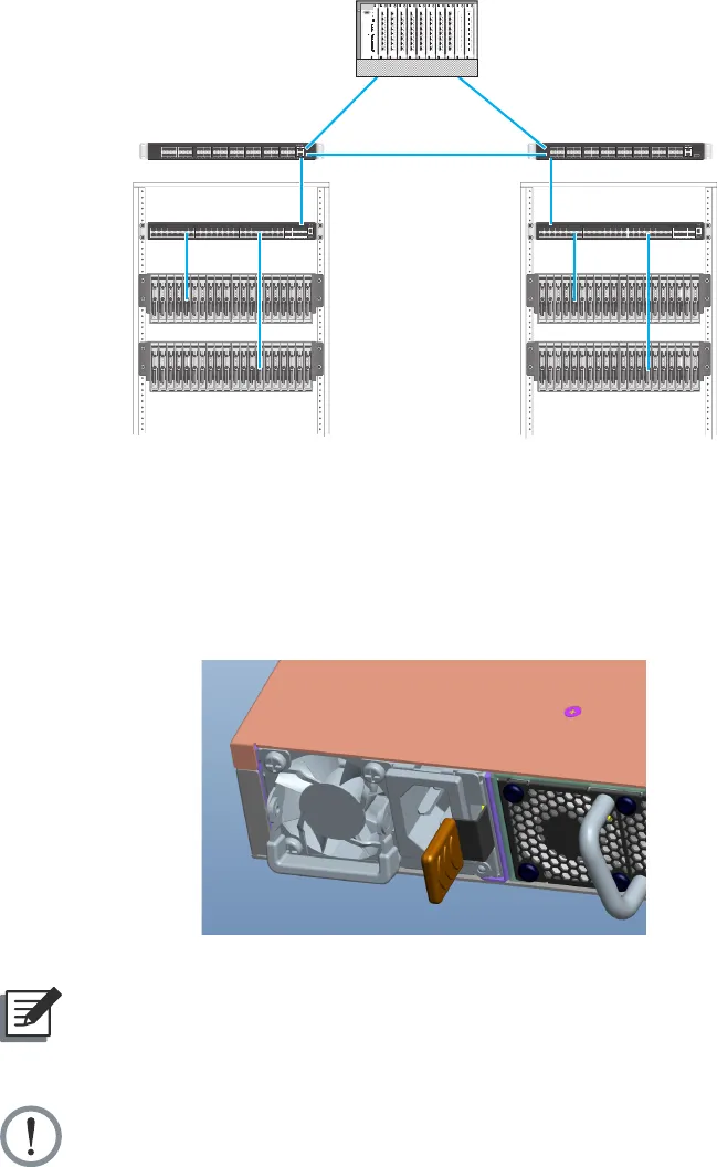
2.5 Power Supply Modules
The power supply modules are hot-swappable power supply units (PSUs) for the switch.
You can install up to two PSUs. The PSUs operate in a load-sharing mode and provides 1+1
redundancy.
(Figure 2-7: Power Supply Unit)
NOTE:
1+1 redundancy is a system where a switch power supply is backed up by
another switch power supply in a load-sharing mode. If one power supply fails,
the other power supply takes over the full load of the switch.
WARNING:
• The switch includes plug-in power supply and fan tray modules that are
installed into its chassis. All modules must have a front-to-back airow
direction, or back-to-front airow direction.
• Risk of explosion if battery is replaced by an incorrect type. Dispose of used
batteries according to the instructions.
• Remove the power cable from the module prior to removing the module
itself. Power cable must not be connected prior to insertion in the chassis or
equivalent.


