6
• Appearance and MechanismChapter 2
2.3 System Requirements
Component Requirement
System requirements
Switch fabric capacity Non-blocking full wire speed on all packet sizes
Forwarding architecture Store and forward or cut-through
Port packet forwarding rate
(at 64 Bytes)
• 14880000 pps (10Gb)
• 1488000 pps (1000 Mb)
MAC address entries
supported
128K entries
Memory type 9 MBytes buffer memory
Console port Serial RS232 console ports (RJ45)
Serial console
• Provide visual feedback of the boot process to the user
• Timeout after period of inactivity
Port requirements
Speed Capability per Port 1G/10Gbps Auto-Sensing
Full-Duplex Flow Control Support the IEEE 802.3x PAUSE frame
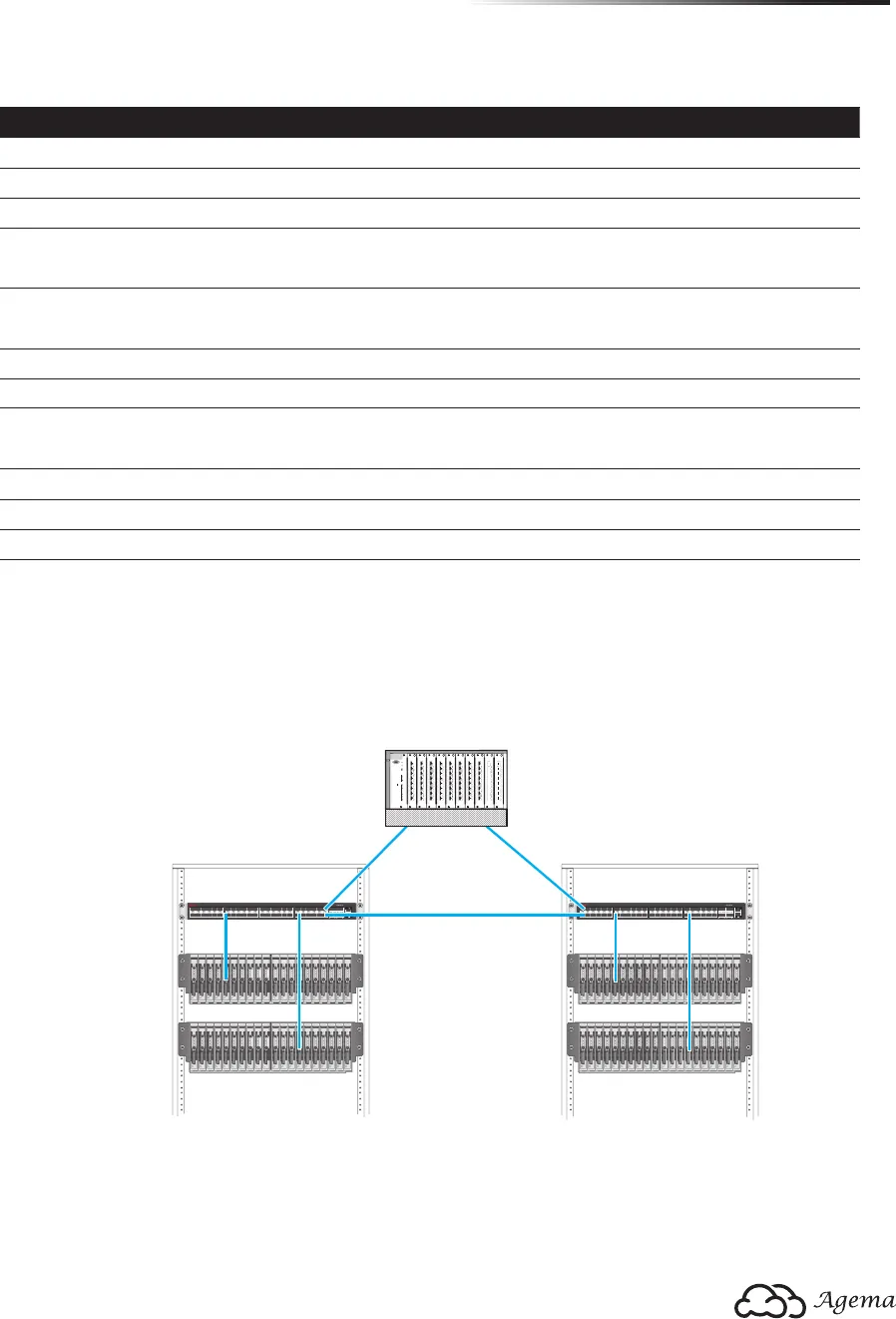
2.4 Data Center Deployment
The following gure illustrates the converaged Ethernet data center deployment.
1357911
246810 12
13 15 17 19 21 23
14 16 18 20 22 24
25 27 29 31 33 35
26 28 30 32 34 36
37 39 41 43 45 47
38 40 42 44 46 48 49 50
51 52
CONSOLE
PWR1PWR2 SYSTEMFAN
MGMT
AG-7448PL
1357911
246810 12
13 15 17 19 21 23
14 16 18 20 22 24
25 27 29 31 33 35
26 28 30 32 34 36
37 39 41 43 45 47
38 40 42 44 46 48 49 50
51 52
CONSOLE
PWR1 PWR2SYSTEMFAN
MGMT
AG-7448PL
srevreS edalBsrevreS edalB
hctiwS RoThctiwS RoT
Core Switch
Console
Reset
Clear
Mode
Select
Act
Fdx
100
SwitchEngineFail
SelfTest
A
X1
Link
Mode
X2
X
3
X4 X
5
X7
X6
X8
A
X
1
Link
Mode
X
2
X3 X4
X
5
X7
X6
X8
A
X1
Link
Mode
X
2
X
3
X
4 X
5
X7X
6
X
8
A
X
1
Link
Mode
X2
X
3
X
4
X
5
X7X
6
X
8
Status
A
I
E
C
1
G
B
J
F
D
2
H
Modules
Power
Fan
A
X
1
Link
Mode
X
2 X3
X
4 X5
X7X
6
X
8
A
X1
Link
Mode
X2
X3
X
4
X
5
X
7
X
6
X8
A
X1
Link
Mode
X
2 X3 X
4
X5
X
7
X
6
X
8
A
X1
Link
Mode
X2 X
3 X
4
X
5
X
7
X
6
X8
A
X
1
Link
Mode
X
2
X3
X
4
X
5
X
7
X
6
X8
A
X1
Link
Mode
X2
X
3
X4 X
5
X7X
6
X
8
(Figure 2-5: Converaged Ethernet Data Center Deployment)


