B: Specifications
270-00000-000- 02-201107 21
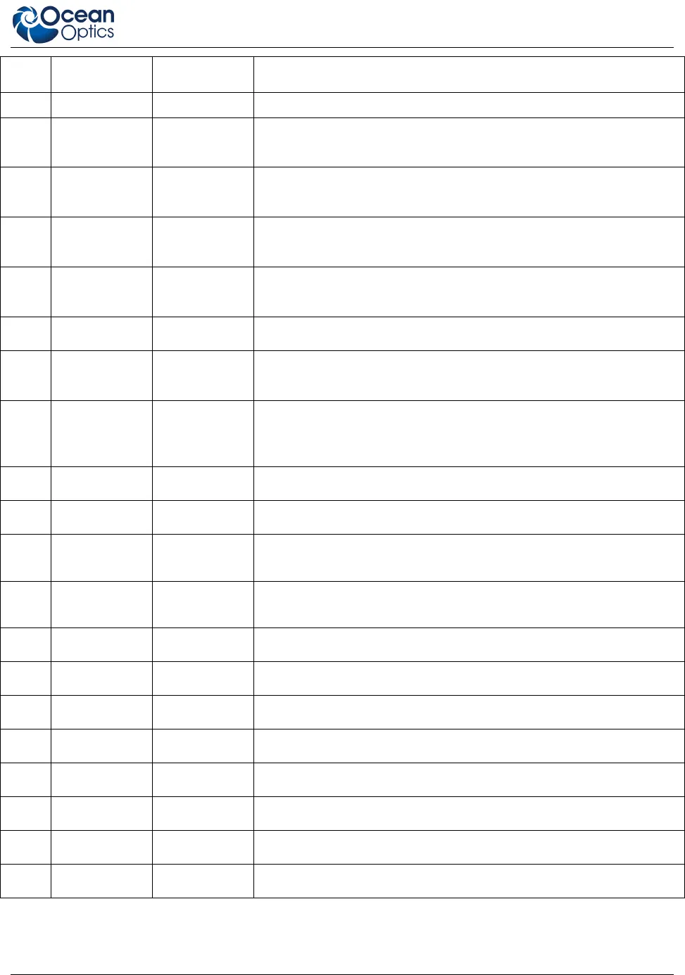
Pin # Function Input/Output Description
5V
IN
Output USB specifications
2 RS232 Tx Output
RS232 transmit signal – Communicates with a computer over DB9
Pin 2
3 RS232 Rx Input
RS232 receive signal – Communicates with a computer over DB9
Pin 3
4 Lamp Enable Output
TTL signal driven Active HIGH when the Lamp Enable command
is sent to the spectrometer
5
Continuous
Strobe
Output
TTL output signal used to pulse a strobe – Divided down from the
master clock signal
6 Ground Input/Output Ground
7
External
Trigger In
Input
TTL input trigger signal – See External Triggering Options
document for info
8 Single Strobe Output
TTL output pulse used as a strobe signal – Has a programmable
delay relative to the beginning of the spectrometer integration
period
9 I
2
C SCL Input/Output The I
2
C clock signal for communications to other I
2
C peripherals.
10 I
2
C SDA Input/Output The I
2
C Data signal for communications to other I
2
C peripherals.
11 MOSI Output
The SPI Master Out Slave In (MOSI) signal for communications to other
SPI peripherals
12 MISO Input
The SPI Master In Slave Out (MISO) signal for communications to other
SPI peripherals
13 GPIO-1 Input/Output
Master clock
14 GPIO-0 Input/Output
Base clock
15 GPIO-3 Input/Output
Integration clock
16 GPIO-2 Input/Output
Reserved
17 GPIO-5 Input/Output
Acquire spectra (Read Enable)
18 GPIO-4 Input/Output
Reserved
19 GPIO-7 Input/Output
SH CCD pin
20 GPIO-6 Input/Output
ICG CCD pin


