Advantech SOM-Express Design Guide
102 Chapter 8 Heat Sink Recommended Design
Alternative material can be used at the users’ discretion. The entire heatsink
assembly, including the heatsink, attach method, and thermal interface material,
must be validated together for specific applications.
8.3 Attachment Method of Thermal Solution
The thermal solution can be attached to the motherboard in a number of ways. The
thermal solutions have been designed with mounting holes in the heatsink base. A
plastic rivet is currently in development that can be used to fasten smaller heatsinks.
For larger and heavier heatsinks, a fastening system consisting of screws, springs,
and secured with a nut should be used. The entire heatsink assembly must be
validated together for specific applications, including the heatsink, attach method,
and thermal interface material.
8.4 Grounding Issues
The mounting holes on all Advantech SOM-Express are connected to digital circuit
ground (GND) for improved EMC performance. Using conductive screws and
distance keepers will also connect the heat spreader and attached heat sink to GND.
In some applications the heat sink or heat spreader will be directly screwed with the
inner surface of the chassis. In some cases, however, it may not be desirable to have
a direct connection of circuit ground (GND) and chassis ground through the heat sink
and / or heat spreader. System designers should take this into account when defining
system grounding.
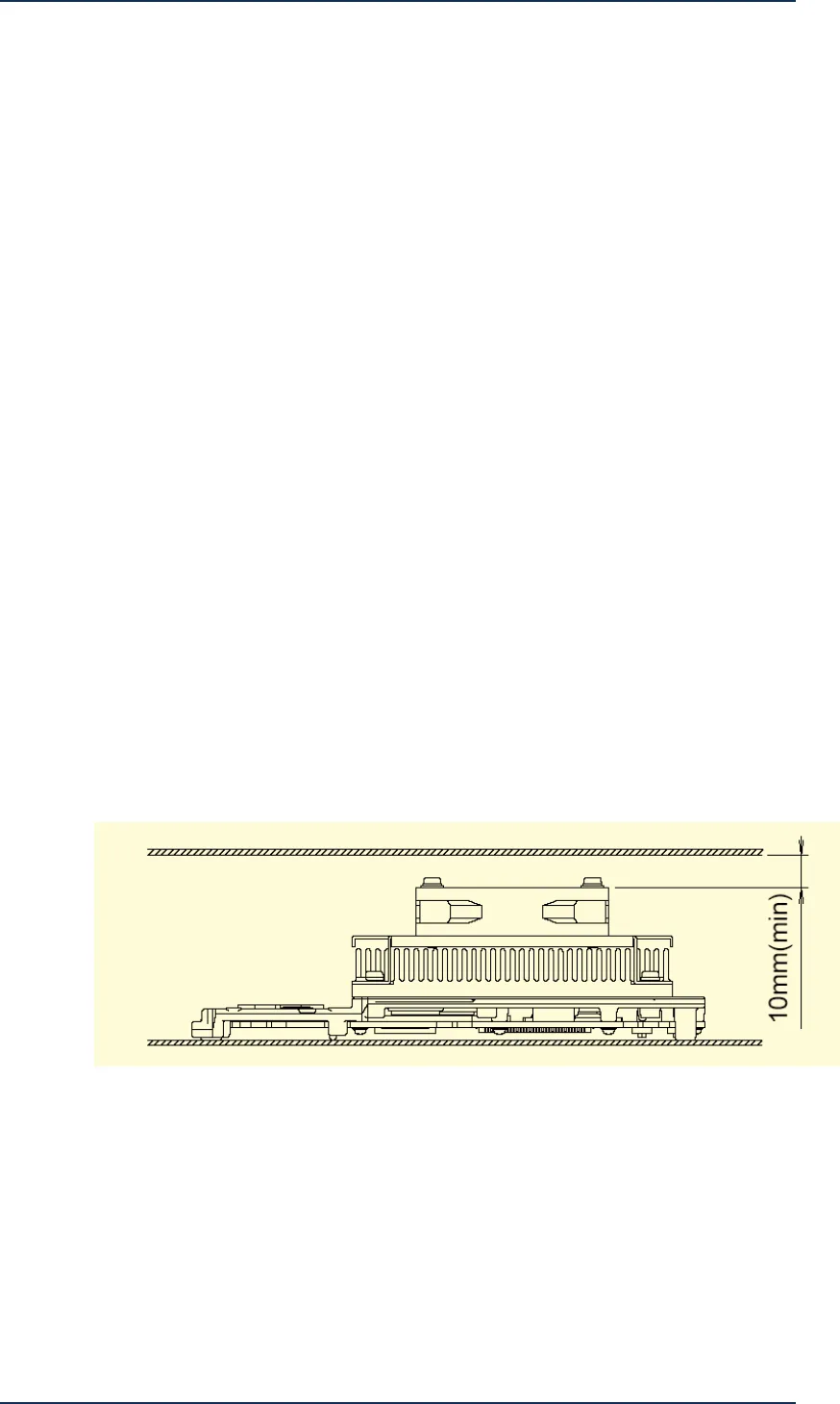
8.5 Air intake clearance and Airflow of Heatsink
The heatsink were designed to maximize the available space within the volumetric
keep-out zone. These heatsinks must be oriented in a specific direction relative to the
processor keep-out zone and airflow. In order to use this design, the processor must
be placed on the PCB in an orientation so the heatsink fins will be parallel to the
airflow.
Figure 8-1: Air Intake Clearance


