AIMB-270 User Manual 18
should be connected to pin 4-5.
There are 3 modes for the power supply connection. The first is “ATX power mode”;
the system turns on/off by a momentary power button. The second is “AT Power
Mode”; the system turns on/off via the power supply switch. The third is another “AT
Power Mode” which makes use of the front panel power switch. The power LED sta-
tus is indicated in the following table:
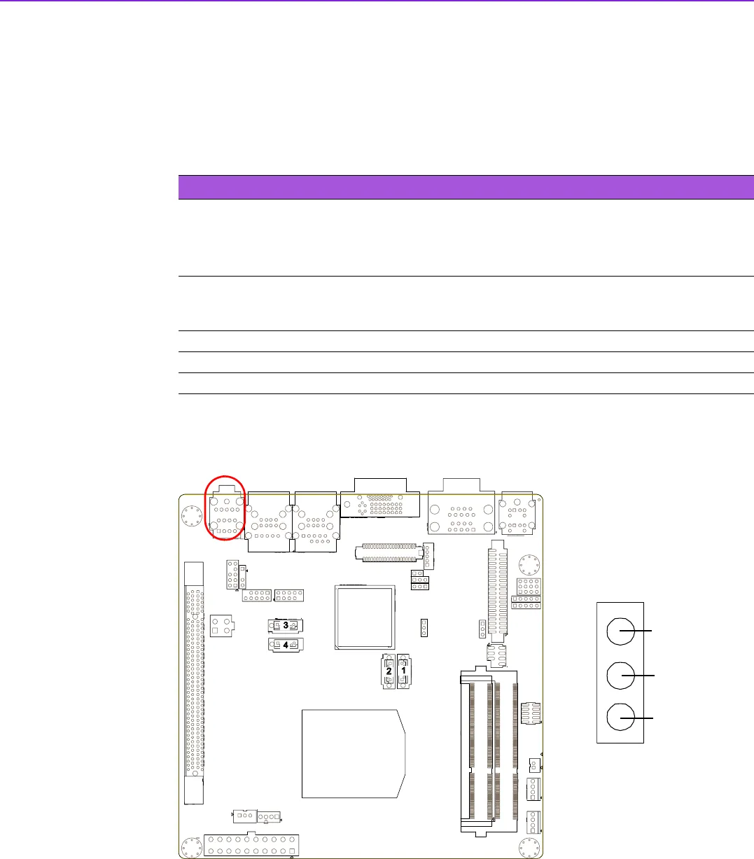
2.9 Line In, Line Out, Mic In Connector (AUDIO1)
Table 2.2: ATX power supply LED status (No support for AT power)
Power mode
LED
(ATX Power Mode)
(On/off by
momentary button)
LED
(AT power Mode)
(On/off by switching
power supply)
LED
(AT power Mode)
(On/off by front
panel switch)
PSON1
(on back plane)
jumper setting
pins 2-3 closed pins 1-2 closed
Connect pins 1 & 2 to
panel switch via cable
System On On On On
System Suspend Fast flashes Fast flashes Fast flashes
System Off Slow flashes Off Off
1
2
3
4
Line Out
Mic In
Line In


