Assembly Instructions for
Chair No. DC410
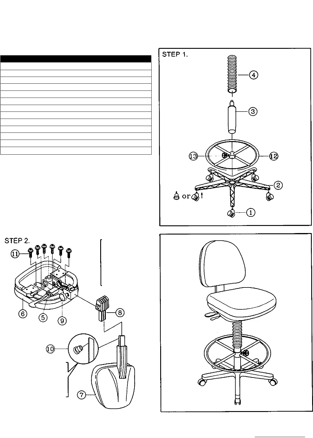
PART LIST
KEY QTY DESCRIPTION
1 5 Casters or Glides
2
1
Base
3
1
Gas Cylinder
4 1
Cylider Cover
5 1 Seat Plate
6 1 Seat
7
1
Backrest + Plastic Cover
8
1 Connector Cover
9 1
Backrest Height Adjustment Knob
10
1
Backrest Stopper
11
6
Seat Plate Screws
12 1
Footrest
13 1
Knob For Footrest
PREVENTIVE MAINTENANCE AND WARNING!
USE THIS PRODUCT ONLY FOR SEATING ONE PERSON AT A TIME.
00 NOT USE THIS CHAIR AS A STEP STOOL / LADDER.
DO NOT USE CHAIR UNLESS ALL BOLTS . SCREWS AND KNOBS ARE
TIGHT . AT LEAST EVERY SIX MONTHS . CHECK ALL BOLTS . SCREWS
AND KNOBS TO BE SURE THEY ARE TIGHT.
’ IF ANY PARTS ARE MISSING . BROKEN . DAMAGED OR WORN . STOP
USE OF THE PRODUCT UNTIL REPAIRS ARE MADE USING FACTORY
AUTHORIZED PARTS.
' FAILURE TO FOLLOW THESE WARNINGS COULD RESULT IN SERIOUS
INJURY.
The Connector
plastic bellow is
(orned on the
side in order to
insert onto the
rear of
seat plate.
y
Put the plastic stopper
into the backrest post
hole, after assembling
backrest post to
Mechanism.
Alvin & Corrpany, Inc. Bloomfield, Ct Grand Prairie, TX www.alvinco.com


