DBK55 8-Channel Frequency-To-Voltage Input Module
Overview …… 2
Features of the DBK55 …… 2
Input Signal Conditioning …… 3
Edge Selection …… 4
Debouncing …… 4
Frequency Measurement …… 5
D/A Conversion …… 6
Hardware Setup …… 6
Configuring the DBK55 Module …… 6
Configuring the Primary Data Acquisition Device …… 10
CE Compliance …… 10
Connecting the DBK55 to Signals and to the Primary Data Acquisition Device …… 11
Software Setup …… 11
Specifications…… 12
Reference Notes:
o Chapter 2 includes pinouts for P1, P2, P3, and P4. Refer to pinouts applicable to your
system, as needed.
o In regard to calculating system power requirements, refer to DBK Basics located near
the front of this manual.
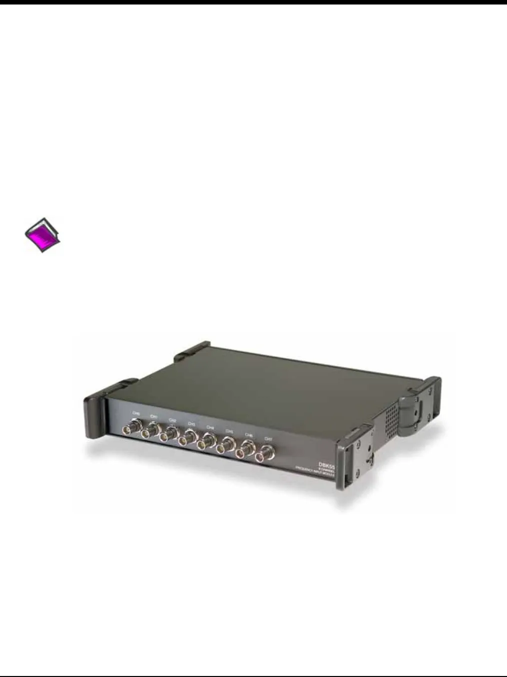
DBK55 Module
DBK Option Cards and Modules 987693 DBK55, pg. 1


