assembly instructions
Item No. 2040 / 2044 / 2045
1. Find a clear area in which you can work.
2. Unpack xture and glass from carton.
3. Carefully review instructions prior to assembly.
1. To install glass panels (5), slip them down through the open top of the cage (4). s - see Drawing
2. Slip bottom of glass panels (5) into channel (6) in bottom of cage (4) tip top of panel into
position, and bend over clips (7) to secure glass in cage. Repeat procedure for remaining panels of
glass.
3. After glass panels are installed, xture may be lamped, and roof parts can be re-installed.
*** The construction of this xture will be accomplished by rst installing the glass, attaching
mounting hardware to the junction box, making all necessary electrical connections, attaching
the xture to the wall.
start here
2044
SAFETY WARNING: READ WIRING AND GROUNDING INSTRUCTIONS (I.S. 18)
AND ANY ADDITIONAL DIRECTIONS. TURN POWER SUPPLY OFF DURING
INSTALLATION. IF NEW WIRING IS REQUIRED, CONSULT A QUALIFIED
ELECTRICIAN OR LOCAL AUTHORITIES FOR CODE REQUIREMENTS.
Drawing 2 - Glass Installation
Make electrical connections from supply wire to xture lead wires. Refer to instruction sheet (I.S. 18)
and follow all instructions to make all necessary wiring connections. Then refer back to this sheet to
continue installation of this xture.
5
6.1.12
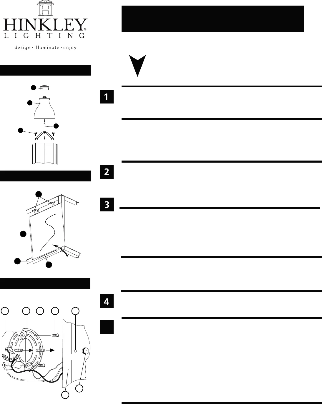
Drawing 3 - Fixture Mounting
2040
2045
7
6
4
5
2
1
2
3
2
4
2
2
Drawing 1 - xture assembly
1. To install glass, it is necessary to remove the roof (2) rst. This is accomplished by rst unthread-
ing top knob (1) - see Drawing 1.
2. Roof (2) can now be lifted o the cage of the xture.
3. To remove cross bar and center tube assembly (3), unthread ball knob studs (4).
4. Set these parts aside in a safe place to be re-installed later.
A
J
B C D
E
F
back plate
1. Prepare mounting strap (A) by threading the two long mounting screws (B)
into the back of the mounting strap (A) - see Drawing 3.
• Be sure the holes into which the screws are threaded match the spacing of holes (D)
in the backplate (E).
2. Attach mounting strap (A) to junction box (J) using two screws (C).
3. To mount xture, slip the two mounting screws (B) through the two mounting holes (D) in the
backplate (E) - see Drawing 3.
4. While holding xture in place, thread the two ball knobs (F) on to the end of the mounting
screws (B), and tighten.
HINKLEY LIGHTING Pin Oak Parkway, Avon Lake, OH 44012 800.446.5539 www.hinkleylighting.com


